
Geocomposite evapotranspiration plugged structure of refuse landfill

A technology for landfill and garbage, which is applied in landfill technology, solid waste removal, etc., can solve problems such as water storage capacity limitations, and achieve the effects of convenient construction, wide applicability, and ability to withstand uneven settlement

Inactive Publication Date: 2010-08-25
SHANGHAI UNIV
View PDF0 Cites 3 Cited by
  • Summary
  • Abstract
  • Description
  • Claims
  • Application Information

AI Technical Summary

Problems solved by technology

However, the water storage capacity of the vegetation growth soil layer is limited by the field water holding capacity of the soil, and the water exceeding the field water holding capacity will continue to infiltrate into the landfill, which leads to the fact that the general evacuation cap is currently only used in arid-semi-arid areas

Method used


Image

  • Geocomposite evapotranspiration plugged structure of refuse landfill
  • Geocomposite evapotranspiration plugged structure of refuse landfill
  • Geocomposite evapotranspiration plugged structure of refuse landfill

Examples


Embodiment 1

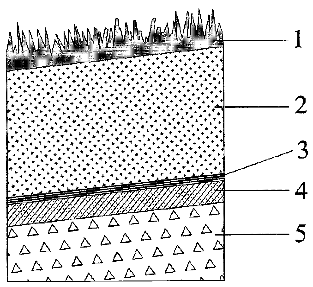
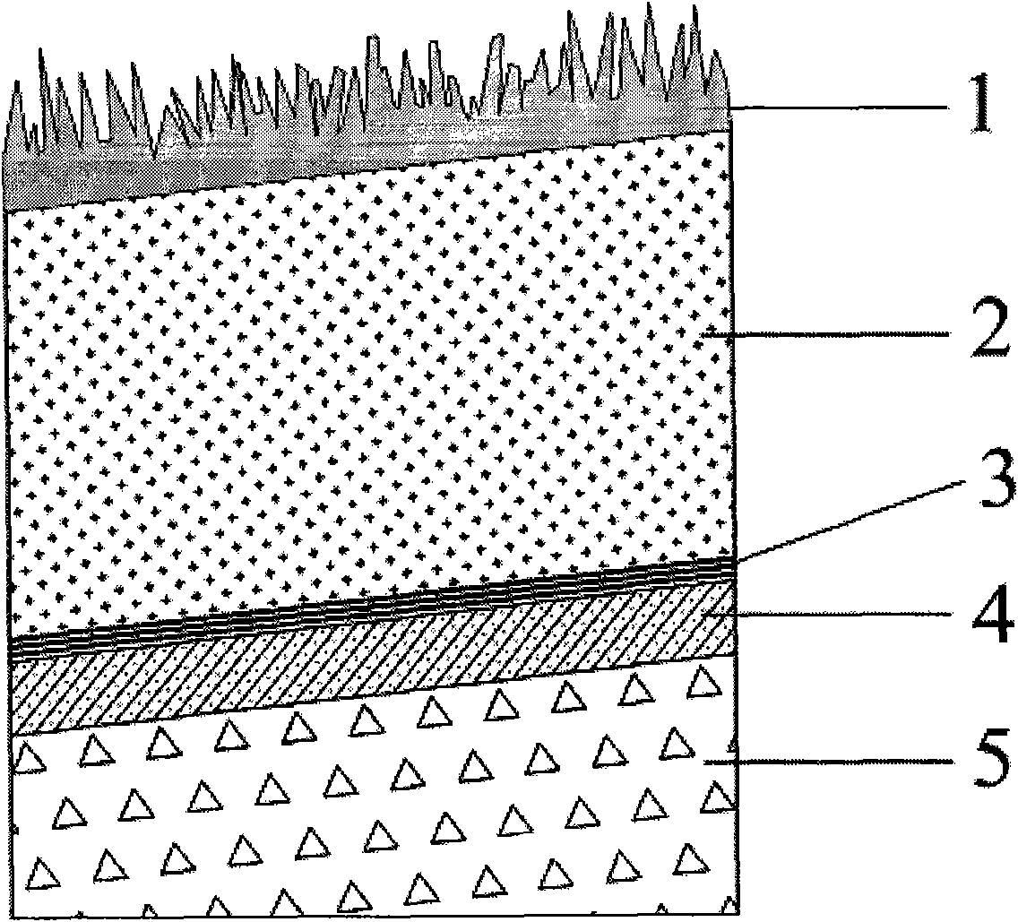
[0015] Embodiment one: referring to Fig. 2, the geotechnical composite capping structure of this refuse landfill includes covering the regulating soil layer 4, the vegetation growth soil layer 2 and the vegetation layer 1 from bottom to top on the garbage 5, and adjusting the soil layer 4 and the vegetation layer 1. A layer of geotechnical composite bentonite pad 3 is laid between the vegetation soil layers 2 .

Embodiment 2

[0016] Embodiment two: referring to Fig. 2, this embodiment is basically the same as embodiment one, and the special features are as follows:

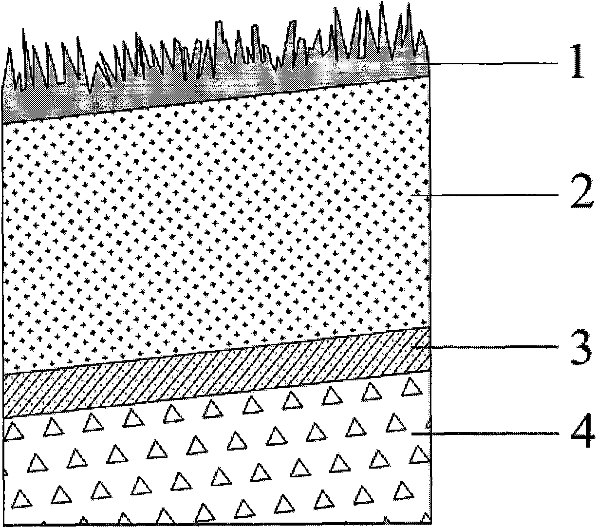
[0017] The geotechnical composite bentonite pad 3 is a sandwich-type composite soil pad with calcium-based or sodium-based bentonite sandwiched between two layers of geotextiles, and its thickness is 5 mm to 10 mm. Vegetation layer 1 is evergreen vegetation, or mixed vegetation of vegetation and shrubs. Vegetation growth soil layer 2 is a single soil layer with strong water holding capacity and suitable for vegetation growth or multi-layer soil containing humus, slag and the like. The regulating soil layer 4 is fine-grained soil for leveling and protection, or fine-grained and coarse-grained double-layered soil for air conduction.


PUM


Abstract

The invention relates to a geocomposite evapotranspiration plugged structure of a refuse landfill, which comprises an adjustment soil layer, a vegetation growth soil layer and a vegetation layer which cover the refuse from bottom to up, wherein a layer of geocomposite bentonite pad is laid between the adjustment soil layer and the vegetation growth soil layer. The geocomposite evapotranspiration plugged structure can obviously enhance water retention capability of an evapotranspiration covered soil layer, lower rainfall infiltration amount after the landfill is sealed, and expand the application of the evapotranspiration plugged structure in sub-humid-humid areas.

Description

technical field [0001] The invention relates to a geotechnical composite vent capping structure for a landfill site, belonging to the technical field of landfill disposal. Background technique [0002] Reducing rainfall infiltration is the main purpose of landfill capping. Traditional capping includes multi-layer structures such as anti-scour vegetation layer, drainage layer, compacted clay layer (or geomembrane plus compacted clay layer), air-conducting layer, etc., using the low permeability of compacted clay layer or geomembrane to prevent water infiltration . The disadvantage is that the compacted clay layer is easy to crack, and the addition of geomembrane often causes the cover soil layer to slip and become unstable, which makes the traditional capping cost higher and the anti-seepage effect is not ideal. [0003] General evapotranspiration capping, as an alternative type of capping, began its application in the 1990s. It uses the capillary action in the vegetation g...

Claims


Application Information

Patent Timeline
Patent Type & Authority Applications(China)
IPC IPC(8): B09B1/00
CPCY02W30/30
Inventor 张文杰邱清文张孟喜
Owner SHANGHAI UNIV
Learn More