
Unit-combination type heat transfer enhancement device

An enhanced heat transfer and combined technology, applied in the direction of cleaning heat transfer devices, heat transfer modification, heat exchange equipment, etc., can solve the problems of complex mold structure, increased flow resistance, shortened service life, etc., and achieve small space , flow resistance is small, and the effect of reducing manufacturing cost

Active Publication Date: 2010-08-25
山西英蓝科技有限公司
View PDF1 Cites 22 Cited by
  • Summary
  • Abstract
  • Description
  • Claims
  • Application Information

AI Technical Summary

Problems solved by technology

However, because its structure is a continuous screw flight design, when the working medium flows in the heat transfer tube, under the working condition of a certain flow rate, the rotation speed of the rotor is determined by the helix angle of the screw flight. Smaller, that is, the shorter the screw lead, the faster the rotor rotates, but at the same time its flow resistance also increases
When the rotation speed of the rotor is high, for example, above 200 rpm, the fluid in the heat transfer tube will cause turbulent flow under the disturbance of the screw edge, and the effect of enhancing heat transfer is remarkable. However, the problem of increased flow resistance is also very prominent. The test shows that in a heat transfer tube with a length of 8 meters and a diameter of 23 mm, the heat transfer tube with a triangular rotor with a lead of 100 mm is compared with the light tube, and the flow area is reduced at the same power pumping. conditions, the flow rate is reduced by more than 30%
Although the problem of increased flow resistance can be alleviated to a certain extent by opening holes on the screw edge, it brings a series of problems such as complex mold structure, increased manufacturing cost, and shortened service life to the molding process.

Method used


Image

  • Unit-combination type heat transfer enhancement device
  • Unit-combination type heat transfer enhancement device
  • Unit-combination type heat transfer enhancement device

Examples


Embodiment Construction

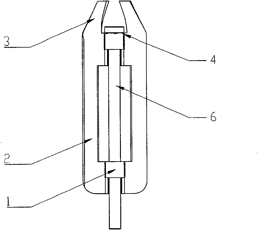
[0027] As shown in Figures 1 to 3, an embodiment of a unit combined heat transfer enhancement device related to the present invention includes a rotor 11, a sleeve shaft 6, a support frame 8 and a connecting axis 10, and the support frame 8 is fixed on The two ends of the heat transfer tube 9 and the two ends of the connection axis 10 are respectively fixed on the support frame 8, and several sleeve shafts 6 are mounted on the connection axis 10 between the two support frames 8, and the rotors 11 correspond to each other one by one. Wearing and sleeve shaft 6 penetrates into the heat transfer tube 9. The rotor 11 is composed of a hinge structure 1, a spoiler blade 2, and a tail screw drive blade 3. The middle part of the hinge structure 1 Hollowed out, with a smooth transition slope at the tail, the hinge structure 1 is surrounded by spoiler rotors 2, the front end of the spoiler rotor 2 is chamfered, and the rear end transitions to the tail screw drive blade 3, as shown in Fig...


PUM


Abstract

A unit-combination type heat transfer enhancement device of the invention relates to the field of the unit type heat transfer enhancement device which utilizes the fluid of a heat transfer pipe as the power, comprising rotors, a support frame, sleeve shafts and a connecting axis, wherein the support frame is fixed at the two ends of the heat transfer pipe; the two ends of the connecting axis are respectively fixed on the support frame; the centers of the sleeve shafts are through holes; a plurality of the sleeve shafts are arranged on the connecting axis in a penetrating manner; the rotors are arranged on the sleeve shafts in a penetrating manner; and one or more rotors is / are matched with one sleeve shaft. The rotor consists of flow-disturbing rotary vanes, a hinge structure and tail end spiral drive blades. The fluid in the pipe in the technical scheme drives the rotors to rotate at a proper speed by the tail end spiral drive blades, thus having the inhibiting and cleaning effects on the fouling deposit; the proportion of the length of the flat and straight part of the flow-disturbing rotary vane and that of the tail end spiral drive blades can be changed flexibly; and according to the practical needs, bulges are also arranged on the thin sheet of the edge to further disturb the fluid to flow, thus further improving the effects of the heat transferring and self cleaning.

Description

technical field [0001] The invention relates to an interpolation element used in heat transfer tubes for anti-fouling and heat transfer enhancement in shell-and-tube heat exchangers, heat exchange reactors, etc. Enhanced heat transfer device field. Background technique [0002] A large number of shell-and-tube heat exchangers, such as condensers and evaporators, are used in petrochemical, electric power, metallurgy, papermaking, food and many other fields. During the production process of these heat exchangers, due to the thick stagnant boundary layer in the area near the tube wall, which affects the heat exchange efficiency, and the ubiquitous dirt on the surface of the heat exchange surface, the heat transfer efficiency is greatly reduced and the energy consumption is significantly increased. For this reason, it is usually necessary to take passive measures to stop production and clean, which greatly reduces production efficiency. ZL95236063 discloses a patent applicatio...

Claims


Application Information

Patent Timeline
Patent Type & Authority Applications(China)
IPC IPC(8): F28G3/00F28F13/12
Inventor 殷淑桂孙广和
Owner 山西英蓝科技有限公司
Learn More