Spraying device of liquid material thin film and spraying method thereof

A material film, spraying device technology, applied in the direction of photo-engraving process coating equipment, etc., can solve the problems of easy fatigue damage of materials, unable to meet industrial production, unable to meet the requirements of nozzle design life and so on

Inactive Publication Date: 2010-08-25
TSINGHUA UNIV
View PDF10 Cites 11 Cited by
  • Summary
  • Abstract
  • Description
  • Claims
  • Application Information

AI Technical Summary

Problems solved by technology

Under the condition that the average diameter of the atomized particles is tens of microns, the atomized flow rate is very small, no more than 800 milliliters per minute, and if it is reduced by ten times, the production efficiency will be greatly reduced, which cannot meet the needs of industrial production; at the same time, ultrasonic The higher the frequency, the smaller the size of the piezoelectric wafer of the corresponding ultrasonic transducer, the amplitude of the atomized surface is correspondingly reduced, and the atomization ability is also significantly reduced; moreover, the higher the ultrasonic frequency, the larger the ultrasonic horn The higher the vibration frequency, the higher the strength requirements for the materials that make up the nozzle, and the materials are more prone to fatigue damage, which cannot meet the design life requirements of the nozzle
Therefore, it is actually not feasible to use high-frequency ultrasonic atomizing nozzles to prepare thin films of liquid materials in industrial applications.

Method used


Image

  • Spraying device of liquid material thin film and spraying method thereof
  • Spraying device of liquid material thin film and spraying method thereof
  • Spraying device of liquid material thin film and spraying method thereof

Examples


Embodiment

[0057] This embodiment specifically describes the spraying device and method for realizing photoresist film according to the technical solution of the present invention.

[0058] First of all, the spraying device for the photoresist film adopts a working form similar to that of an ultrasonic humidifier. The high-frequency mechanical oscillation generated by the ultrasonic oscillator is directly transmitted to the liquid surface through the liquid, and surface tension waves are formed on the liquid surface, which can be obtained For finer atomized particles, multiple such ultrasonic oscillators can be installed to obtain the required amount of ultrasonic atomization.

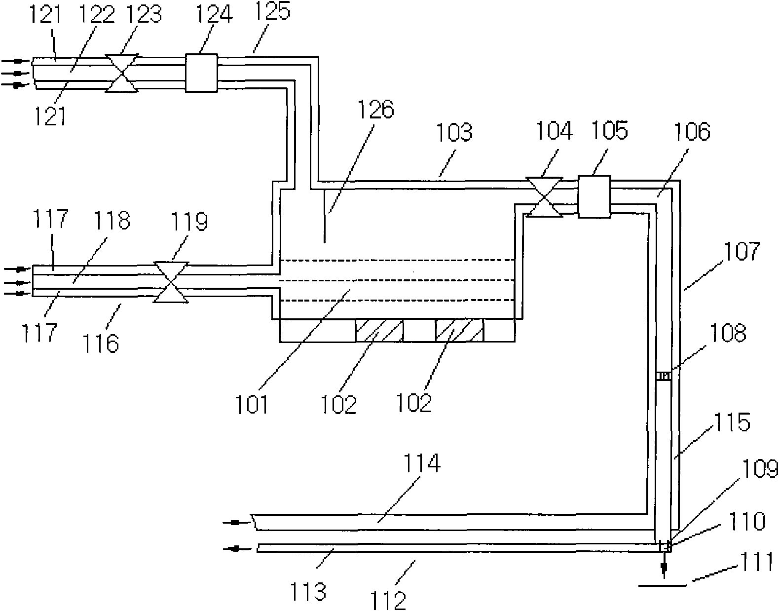
[0059] As shown in Figure 1, the spraying device includes:

[0060] The atomization container 103 is used to contain the photoresist solution 101 and provide an atomization space;

[0061] The ultrasonic vibrator is arranged at the bottom of the atomization container 103 and includes several ultrasonic oscillati...


PUM


Abstract

The invention relates to a spraying device of a liquid material thin film and a spraying method thereof, which belong to the technical field of semiconductor device production. The invention aims to solve the problem that sufficient atomization flow can not be ensured while enough thin ultrasonic atomization liquid particles are obtained. The spraying device comprises an atomization container, an ultrasonic vibration generator used for carrying out ultrasonic atomization operation, a liquid material input device used for introducing liquid raw materials, a carrier gas input device used for introducing carrier gas, a fog output device used for outputting fog and a spray nozzle used for receiving the fog and spraying the fog to a wafer to be sprayed, wherein the carrier gas is used for being mixed with the particles which is formed after the liquid materials are atomized to form the fog. The technical scheme has the characteristics that each functional module is independently installed in the scheme, and thereby, the overall work capacity and efficiency of the device are improved, and the waste of the liquid materials is greatly reduced, and then the environmental pollution is reduced; the thinner and evener spraying effect can be obtained, and a liquid thin film which is thinner and has better evenness can be generated; the spraying device can be used for spraying step surfaces.

Description

technical field [0001] The invention belongs to the technical field of semiconductor device production, and in particular relates to a liquid material film spraying device and a spraying method thereof. Background technique [0002] Photolithography is a very critical process in the production process of semiconductor devices. The quality of its photoresist mask greatly affects the quality of photolithography. The traditional method of preparing photoresist masks is to use the method of rotation, which will soon need to smear The photoresist material is dropped on the center of the wafer, and the wafer is rotated. After the solvent in the photoresist evaporates, a thin film is finally formed on the surface of the wafer, that is, a mask. There is a serious waste phenomenon in this process method. Most of the photoresist is thrown out, leaving only a very small amount of a thin layer of photoresist on the wafer surface. A photoresist film is formed on the surface. As the size...

Claims


Application Information

Patent Timeline
Patent Type & Authority Applications(China)
IPC IPC(8): G03F7/16
Inventor 段广洪向东瞿德刚牟鹏何磊明
Owner TSINGHUA UNIV
Why Eureka
Try Eureka