Method and device for preparing working layer of metallurgical hot roll by laser direct deposition

A working layer and hot roll technology, which is applied in the application field of laser technology to achieve the effect of reducing unit cost, reducing scattering and saving materials

Inactive Publication Date: 2010-09-01
JIANGSU UNIV
View PDF3 Cites 37 Cited by
  • Summary
  • Abstract
  • Description
  • Claims
  • Application Information

AI Technical Summary

Problems solved by technology

So far, there is no report on the research results of the application of laser-assisted direct metal deposition technology to prepare the working layer of hot rolling rolls

Method used


Image

  • Method and device for preparing working layer of metallurgical hot roll by laser direct deposition
  • Method and device for preparing working layer of metallurgical hot roll by laser direct deposition
  • Method and device for preparing working layer of metallurgical hot roll by laser direct deposition

Examples


Embodiment 1

[0040] Example 1: High-speed steel-like powder

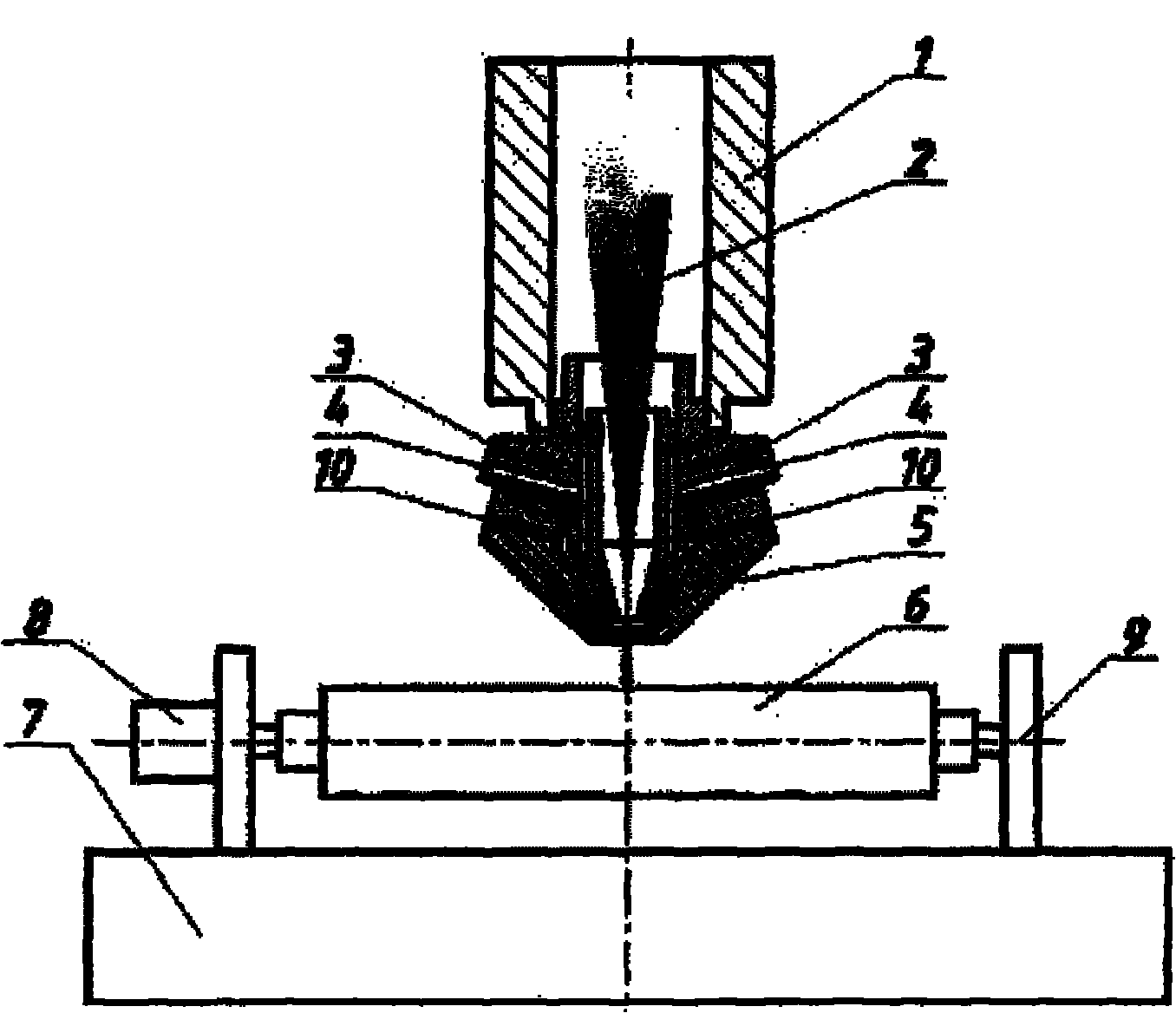
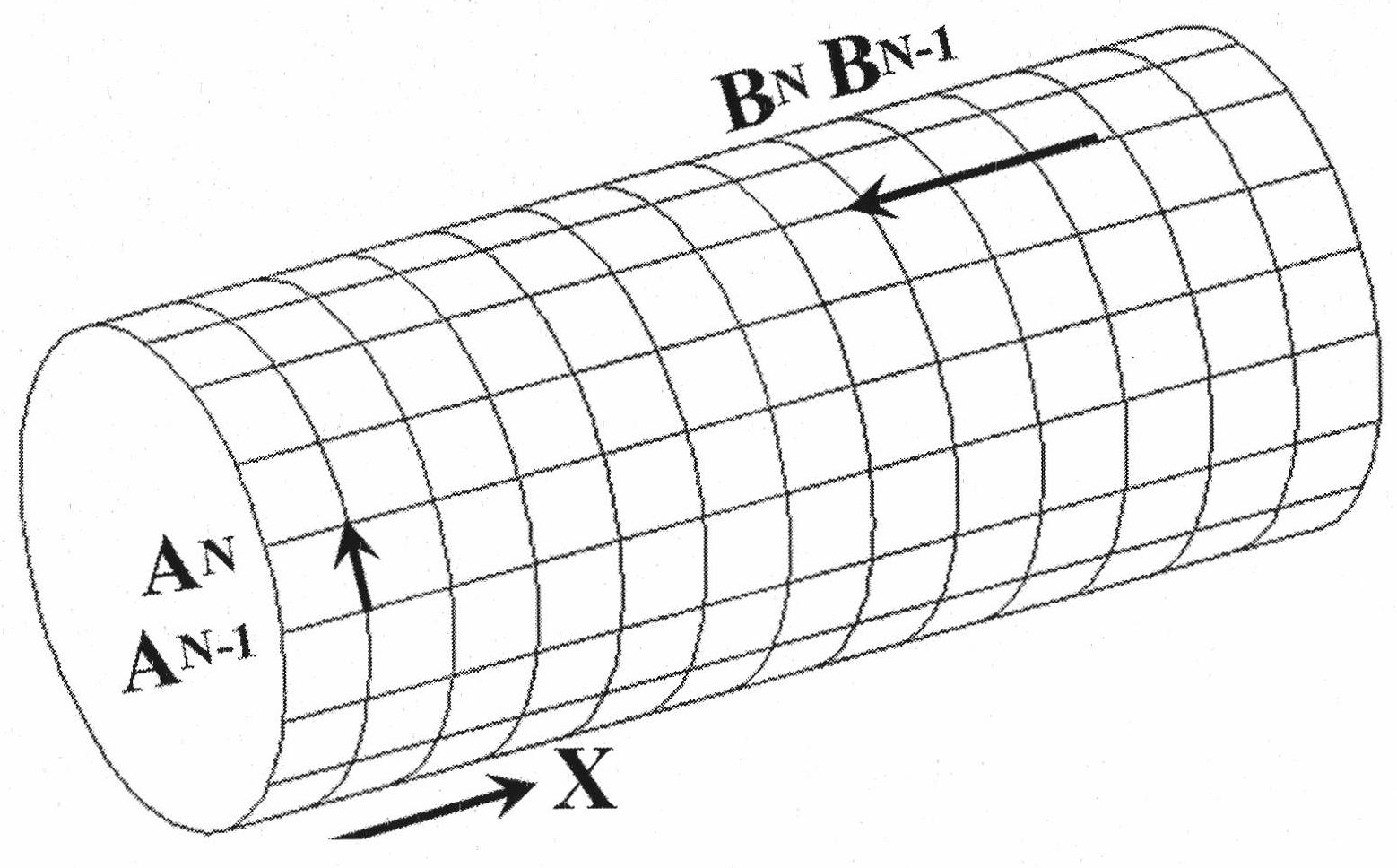
[0041] Use gasoline, alcohol, etc. to remove oil and decontamination solvents to remove oil and rust on the surface of the roller core, and then use sandpaper to polish the surface of the roller core to further remove dirt and facilitate the deposition of the deposition layer; then put the mechanically mixed powder to be deposited into the powder feeding system, adjust the shielding gas, powder feeding gas flow rate and powder flow control system to obtain the required powder flow; open the CO 2 Laser for powder deposition on the surface of the roll core. like image 3 As shown, first deposit along the axial direction of the roll (X direction), and then pass A N and previous pass A N-1 Carry out overlapping, after depositing the entire roll side, start depositing along the roll circumference direction at the end point, the subsequent pass B N with previous pass B N-1 Carry out the overlap of the same overlap rate in the sam...

Embodiment 2

[0043] Example 2: Co-based alloy composite powder

[0044] Use gasoline, alcohol, etc. to remove oil and decontamination solvents to remove oil and rust on the surface of the roller core, and then use sandpaper to polish the surface of the roller core to further remove dirt and facilitate the deposition of the deposition layer; then put the mechanically mixed powder to be deposited into the powder feeding system, adjust the shielding gas, powder feeding gas flow rate and powder flow control system to obtain the required powder flow; open the CO 2 Laser for powder deposition on the surface of the roll core. like image 3 As shown, first deposit along the axial direction of the roll (X direction), and then pass A N and previous pass A N-1 Carry out overlapping, after depositing the entire roll side, start depositing along the roll circumference direction at the end point, the subsequent pass B N with previous pass B N-1 Carry out the overlap of the same overlap rate in the ...


PUM

PropertyMeasurementUnit
particle sizeaaaaaaaaaa
diameteraaaaaaaaaa

Abstract

The invention discloses a method and a device for preparing a working layer of a metallurgical hot roll by laser direct deposition, which belong to the field of the application of laser technology. The method is characterized in that high speed steel-like powder and Co-based alloy composite powder are used as the materials for the working layer of the roll. Concretely, the method comprises: filling high speed steel-like powder or mechanically mixed powder which uses Co-based alloy and the like as a substrate material and is added with reinforcing and toughening submicron grains with different amounts into a powder supply system; and performing laser-assisted direct metal deposition on the surface of a roll core, of which the travel is controlled by a worktable, with synchronous powder supply to manufacture the working layer of the roll. A deposition method adopts an alternate deposition mode. The corresponding deposition thickness is determined according to the requirements on the thickness of the working layer. The hard phase content of the powder, in which the Co-based alloy is added as a hard phase, is increased layer by layer so as to form a gradient deposited layer. In the method, the reinforced, toughened and wear-resistance working layer is prepared on the surface of a cheap hot roll core part material by laser-assisted metal direct deposition technology under specific process conditions.

Description

technical field [0001] The invention belongs to the application field of laser technology, and in particular relates to a method and a device for manufacturing a metallurgical hot roll working layer material by laser direct metal deposition. Background technique [0002] In order to meet the requirements for the performance of hot rolls, the upgrading of hot roll materials and the progress of manufacturing technology are important ways to improve their wear resistance and prolong their service life. The development of hot roll material has experienced a qualitative leap from chilled cast iron to high Cr cast iron, from semi-high-speed steel, high-speed steel to hard alloy. The manufacturing technology of hot rolls has also developed from the traditional forging method to the composite casting method. Centrifugal composite casting, continuous casting outer layer forming method, spray deposition method, hot isostatic pressing, electroslag remelting, surface surfacing and othe...

Claims


Application Information

Patent Timeline
Patent Type & Authority Applications(China)
IPC IPC(8): C23C24/10
Inventor 孙桂芳张永康钱晓明刘常升鲁金忠李鹏
Owner JIANGSU UNIV
Why Eureka
Try Eureka