Method and device for preventing moisture condensation of roof of textile workshop

An anti-condensation and workshop technology, applied in roof insulation materials, heating methods, pipeline layout, etc., can solve problems such as high implementation costs, damage to the workshop production environment, and increased workshop construction costs.

Inactive Publication Date: 2011-10-26
郑州宏大纺纱新技术咨询有限公司
View PDF4 Cites 2 Cited by
  • Summary
  • Abstract
  • Description
  • Claims
  • Application Information

AI Technical Summary

Problems solved by technology

However, this method is expensive to implement, high in maintenance costs, and consumes a large amount of steam. To generate these steams, a large amount of energy is burned, such as coal, oil, and fuel-fired boilers discharge a large amount of carbon dioxide and dust, which seriously pollutes the environment, especially when energy shortages emphasize environmental protection. Today, the National "Eleventh Five-Year" Development Outline and the "Eleventh Five-Year" Planning Outline of the textile industry have put forward strict requirements on energy conservation and emission reduction in the textile industry, and have formulated specific indicators. This anti-condensation method is neither energy-saving nor energy-saving. Not to mention reducing emissions, it also pollutes the environment, and the cost remains high. Fundamentally, it has fallen far behind the development trend of the modern textile industry.
[0007] To solve the dew condensation on the roof of the factory building, we can also start by improving the insulation performance of the roof, adding insulation materials to reduce the heat conduction, increasing the thickness of the insulation materials on the roof, and doing a good job of insulation during construction. The vapor layer is sealed, and the lower surface of the roof is sprayed with anti-condensation paint. However, it has been proved that these methods cannot prevent condensation when the temperature is low in winter, and greatly increase the construction cost of the plant and prolong the construction period, especially for the completed plant. Can be renovated or rebuilt at a higher cost
Improving the ventilation performance of the roof is also a way to prevent condensation on the roof of the factory. Do several rows of natural ventilators to exhaust the air, or install a roof ventilation fan, or erect an electric axial fan on the roof to ventilate and dehumidify to prevent condensation. These methods can only prevent local condensation on the roof, and it is easy to form a short circuit of air flow on the roof, resulting in a large loss of indoor heat, resulting in a drop in workshop temperature, destroying the production environment in the workshop, and affecting product quality. It is not suitable for textile factories with strict temperature and humidity requirements. Applicable, and some equipment is expensive, and the energy consumption is large, which is not in line with the development direction of energy saving and emission reduction in the textile industry

Method used


Image

  • Method and device for preventing moisture condensation of roof of textile workshop
  • Method and device for preventing moisture condensation of roof of textile workshop
  • Method and device for preventing moisture condensation of roof of textile workshop

Examples


Embodiment 1

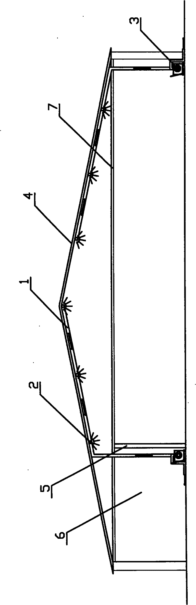
[0070] Embodiment one: the test textile factory of the present invention is a certain textile factory in the north of China, and the plant area is more than 1,000 square meters. The main body is a steel structure building, and the roof is a pointed roof such as figure 1 As shown, the outer surface is thin steel plate, the inner surface is W-C veneer, and the middle insulation material is Owens glass wool. The workshop is equipped with a suspended ceiling and an air-conditioning room. The temperature and humidity in the workshop are adjusted through the air-conditioning system. In winter, the temperature in the workshop is kept at about 25°C, and the relative humidity is 70%. In winter, the high-humidity water vapor in the workshop permeates and diffuses into the ceiling space through the gaps in the ceiling. There are gaps in the W-C veneer layer, and high-temperature and high-humidity water vapor enters the insulation through the gaps. In the material layer, it reaches saturat...

Embodiment 2

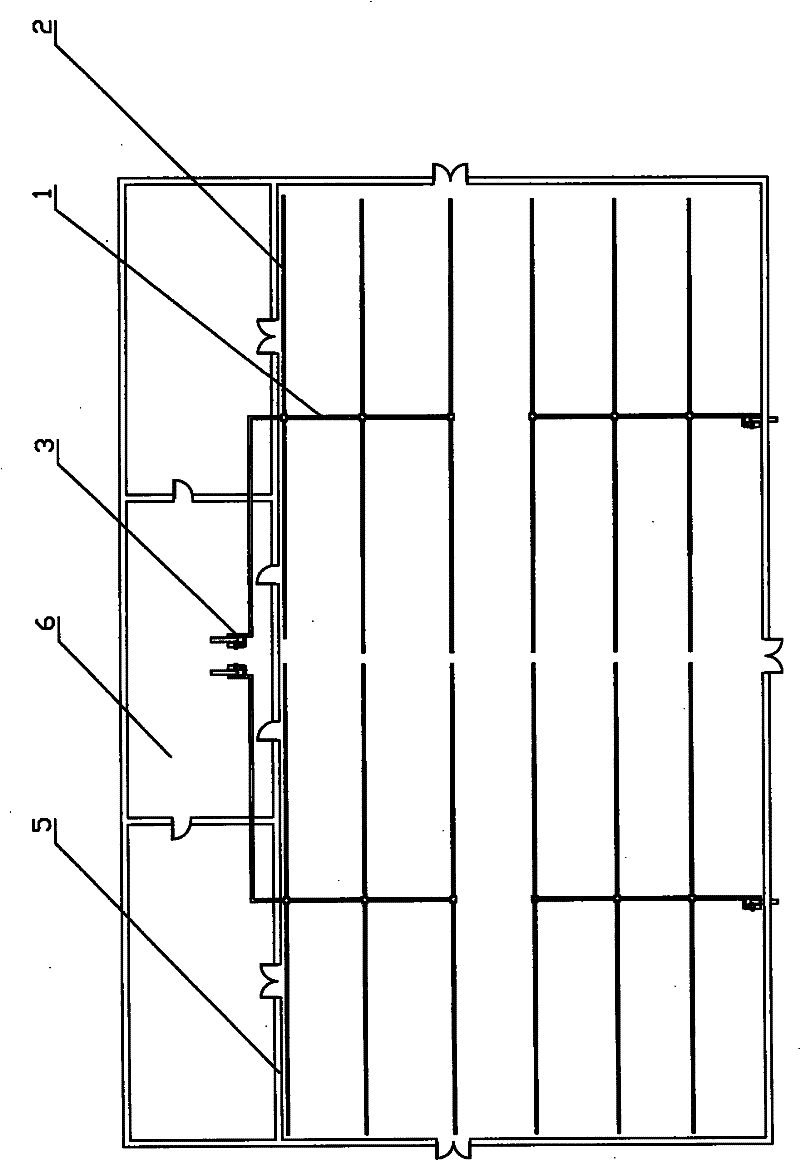
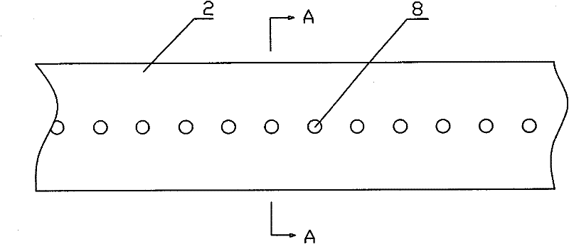
[0086] Embodiment 2: It is basically the same as Embodiment 1, and the similarities will not be repeated. The difference is that the exhaust and dehumidification main pipe and the exhaust and dehumidification branch pipe have equal cross-sections, and each exhaust and dehumidification branch pipe is along the direction of the roof. There are two rows of approximately evenly distributed exhaust and dehumidification holes on each side wall. The distance between the exhaust and dehumidification holes is 150mm, and the distance between the exhaust and dehumidification pipe network and the lower surface of the factory roof is 5mm.

[0087] The method of this embodiment is that when the relative humidity value detected by the humidity sensor reaches 70%, the control circuit starts the exhaust and dehumidifier fan to extract the high-humidity air near the lower surface of the factory roof and send it to the air-conditioning room of the workshop, or directly discharge it outside , when...

Embodiment 3

[0088] Embodiment 3: It is basically the same as Embodiment 1, and the similarities will not be repeated. The difference is that the exhaust and dehumidification branch pipes are connected obliquely to the main pipe, arranged at equal intervals in the oblique direction, and the exhaust and dehumidification branch pipes are connected with the main pipe. The cross-section of the main pipe is equal, the cross-sectional shape is elliptical, and the material is glass steel pipe. Each exhaust and dehumidification branch pipe has two rows of approximately uniformly distributed exhaust and dehumidification holes on both sides of the roof. The shape is elliptical, the distance between the exhaust and dehumidification holes is 50mm, and the distance between the exhaust and dehumidification pipe network and the lower surface of the factory roof is 5mm.

[0089] The method of this embodiment is that when the relative humidity value detected by the humidity sensor reaches 82%, the control c...


PUM


Abstract

The invention discloses a method and a device for preventing moisture condensation of a roof of a textile workshop. The method comprises the following steps of: using an exhausting and dehumidifying fan in winter: starting the exhausting and dehumidifying fan when the air humidity of the roof reaches the highest limit value of the given relative humidity through an exhausting and dehumidifying pipe net fixed at the lower surface of the roof of the textile workshop, and extracting the humid air around the lower surface of the roof. The device comprises the exhausting and dehumidifying pipe netat the lower surface of the roof of the textile workshop, a humidity sensor, the exhausting and dehumidifying fan and an anti-fogging automatic control circuit; the exhausting and dehumidifying pipe net consists of at least one exhausting and dehumidifying main pipe and a certain quantity of exhausting and dehumidifying branch pipes arranged by a certain regular way; the two sides of each exhausting and dehumidifying branch pipe are at least respectively provided with a row of exhausting and dehumidifying holes or seams arranged uniformly. The invention has good effect of preventing moisture condensation, low cost of application, simple structure and convenient use; and the operation fee is only 4% of the traditional method. The invention can save energy and reduce the power consumption, has good environmental-friendly performance and provides great economic benefits and social benefits in the textile industry.

Description

1. Technical field: [0001] The invention relates to the field of ventilation of textile factory buildings, in particular to a method and device for preventing condensation on the roof of textile factory buildings. 2. Background technology: [0002] The textile production process has strict requirements on temperature and humidity, and it is necessary to maintain relatively high temperature and humidity conditions in the workshop. The requirements for temperature and relative humidity of each main process of textile production are shown in the following table: [0003] [0004] In the winter textile workshop, the temperature is generally required to be 21°C-26°C, and the humidity is 60%-75%. Compared with the cold outdoor temperature and low humidity, especially in the northern winter, the air is dry and cold, so the workshop should maintain such high temperature and high humidity. In the production environment, condensation on the roof is prone to occur. Roof condensatio...

Claims


Application Information

Patent Timeline
Patent Type & Authority Patents(China)
IPC IPC(8): E04D13/16F24F7/06F24F13/02F24F11/02
Inventor 王伟民康燕
Owner 郑州宏大纺纱新技术咨询有限公司
Why Eureka
Try Eureka