Gas burner
A gas burner and gas technology, applied in the direction of burner, combustion method, combustion type, etc., can solve the problems of large NOx emissions of flue gas components, uneven burner flame temperature field, insufficient and incomplete combustion of gas, etc. Achieve the effect of compact structure, easy maintenance and favorable utilization of heat energy
- Summary
- Abstract
- Description
- Claims
- Application Information
AI Technical Summary
Problems solved by technology
Method used
Image

Examples
Embodiment Construction
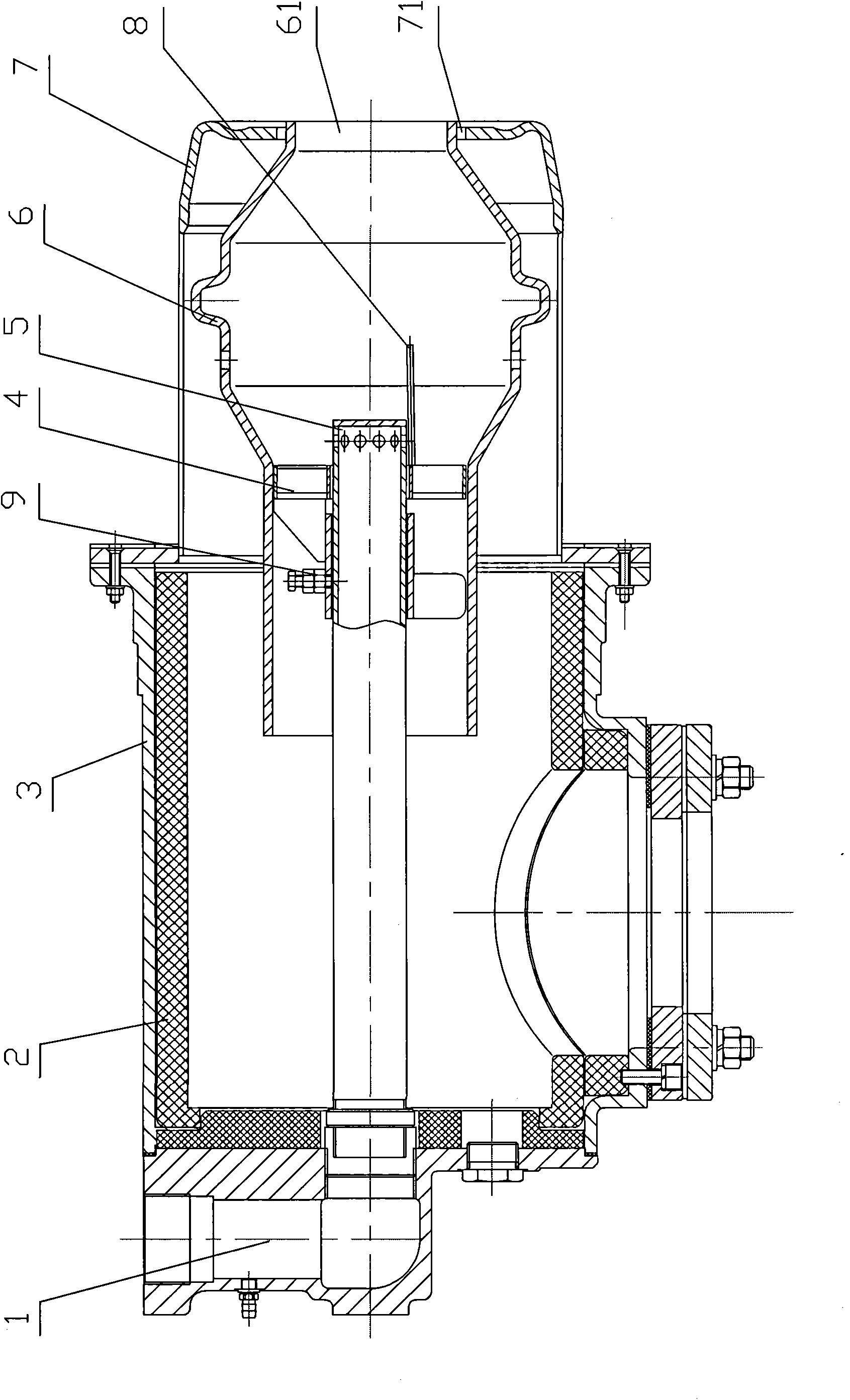
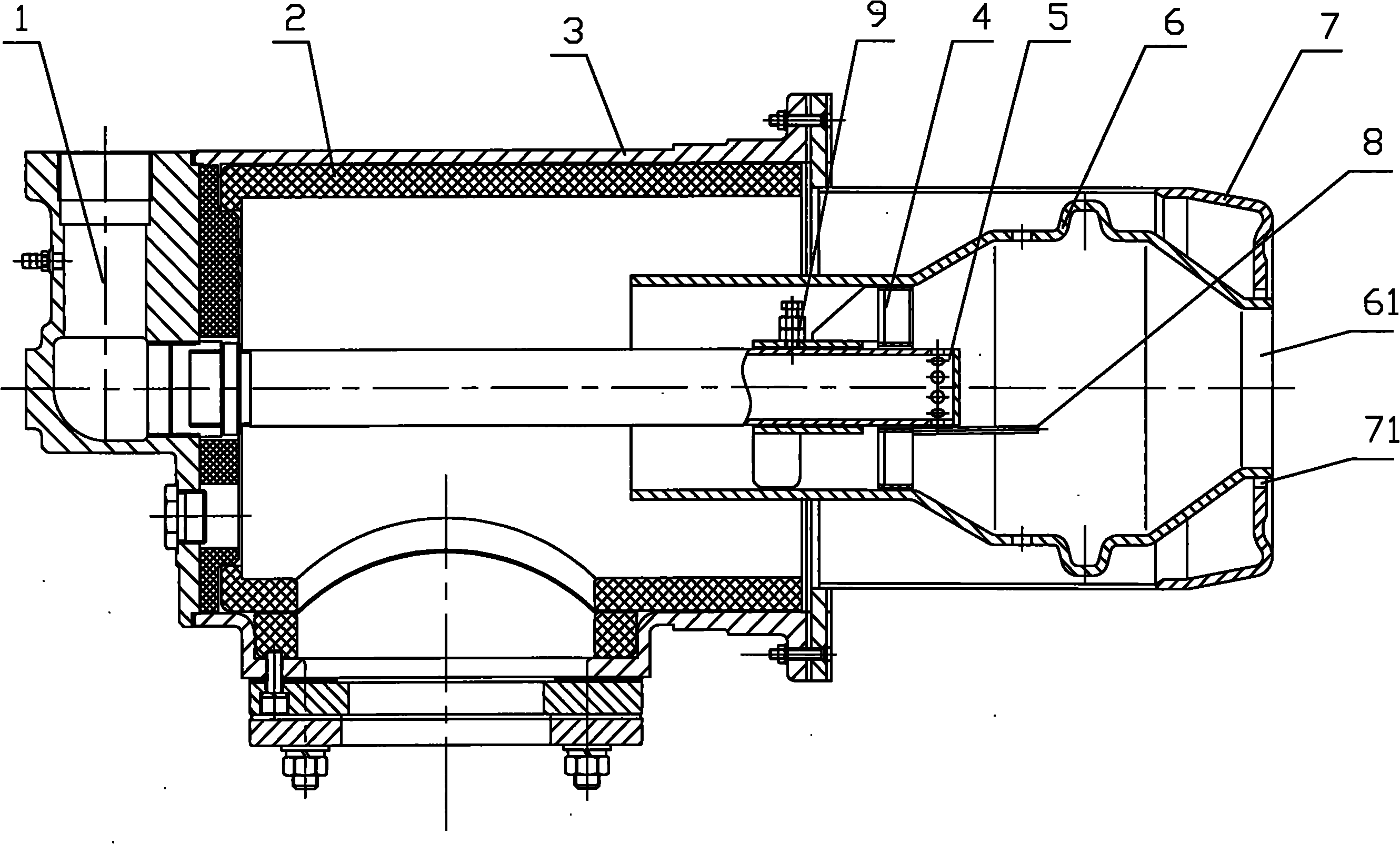
[0009] refer to figure 1 , a gas burner of the present invention, comprising a gas housing 1, a gas pipe 5 communicating with the gas housing 1, an air housing 3 surrounding the periphery of the gas pipe 5, and the front end of the gas pipe 5 is provided with a Electrode 8, the front end of the gas pipe 5 is provided with a combustion chamber 6, the electrode 8 is located in the combustion chamber 6, the rear end of the combustion chamber 6 is connected with the front end of the gas pipe 5 through a wind tray 4, the combustion chamber 6 is connected with the air The housing 3 is connected, and the front end of the combustion chamber 6 is a reduced flame nozzle 61. The periphery of the combustion chamber 6 is provided with an outer tube 7 communicating with the air housing 3. The front end of the outer tube 7 surrounds the flame nozzle 61 An annular combustion-supporting air nozzle 71 is provided on the periphery.
[0010] The above technical solution can also have the followi...
PUM
 Abstract
Description
Claims
Application Information