Automatic control device of infrared ray burner

An automatic control device and an infrared burner technology, applied in the direction of combustion method, combustion control, fuel supply adjustment, etc., can solve problems such as low thermal efficiency of the burner, non-operation, unstable gas pressure, etc., and achieve high cost savings, The best energy-saving effect and the effect of maintaining stability

Inactive Publication Date: 2010-09-01
郑乐斌
View PDF7 Cites 4 Cited by
  • Summary
  • Abstract
  • Description
  • Claims
  • Application Information

AI Technical Summary

Problems solved by technology

[0004] The purpose of the present invention is to provide an automatic control device for an infrared burner, so as to realize the precise control of the combustion state of the ceramic plate, and solve the problems in the prior art that the gas pressure is unstable, tempering and deflagration occur, resulting in low thermal efficiency of the burner, or even failure. work problem

Method used


Image

  • Automatic control device of infrared ray burner
  • Automatic control device of infrared ray burner

Examples


Embodiment Construction

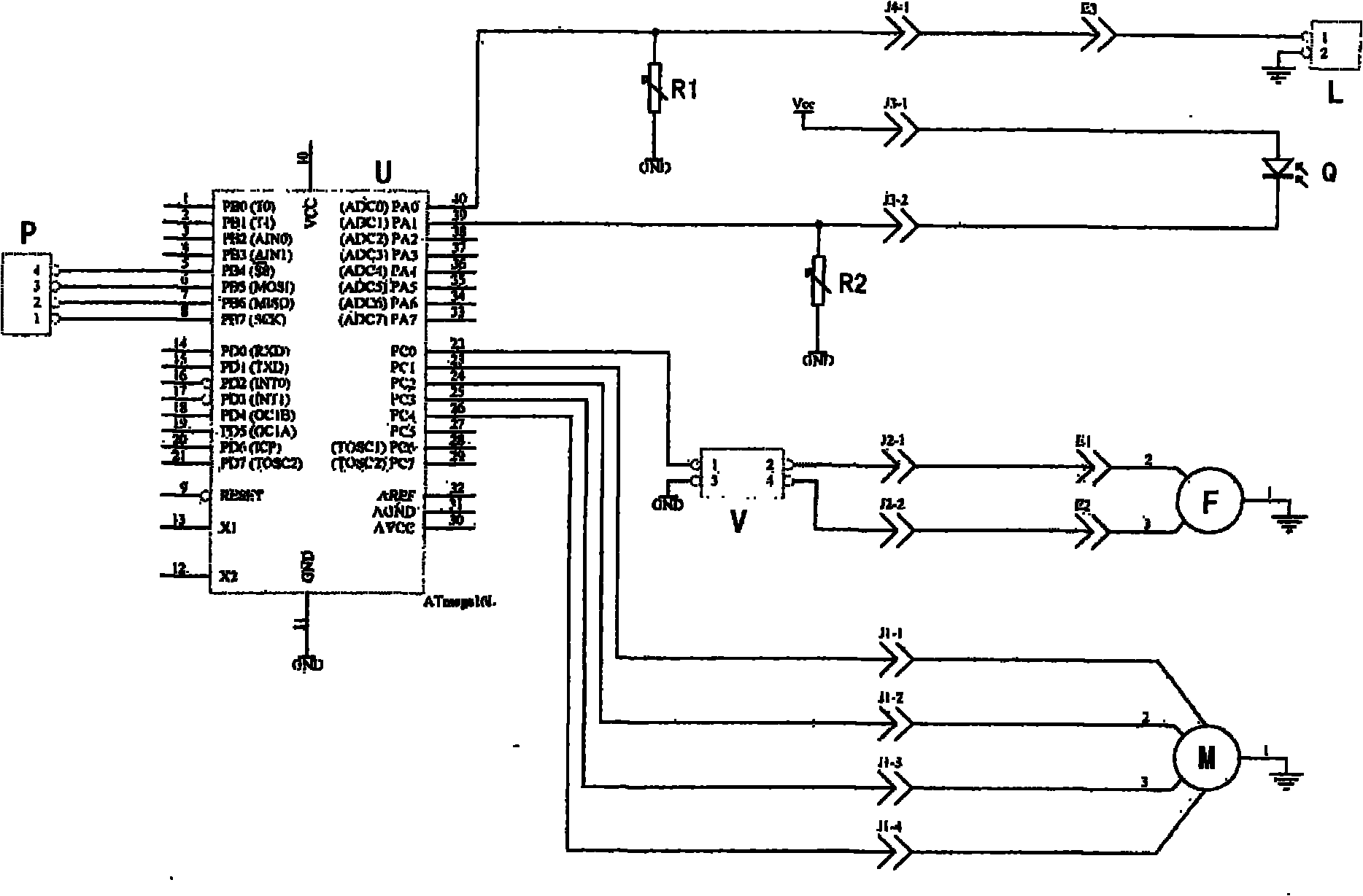
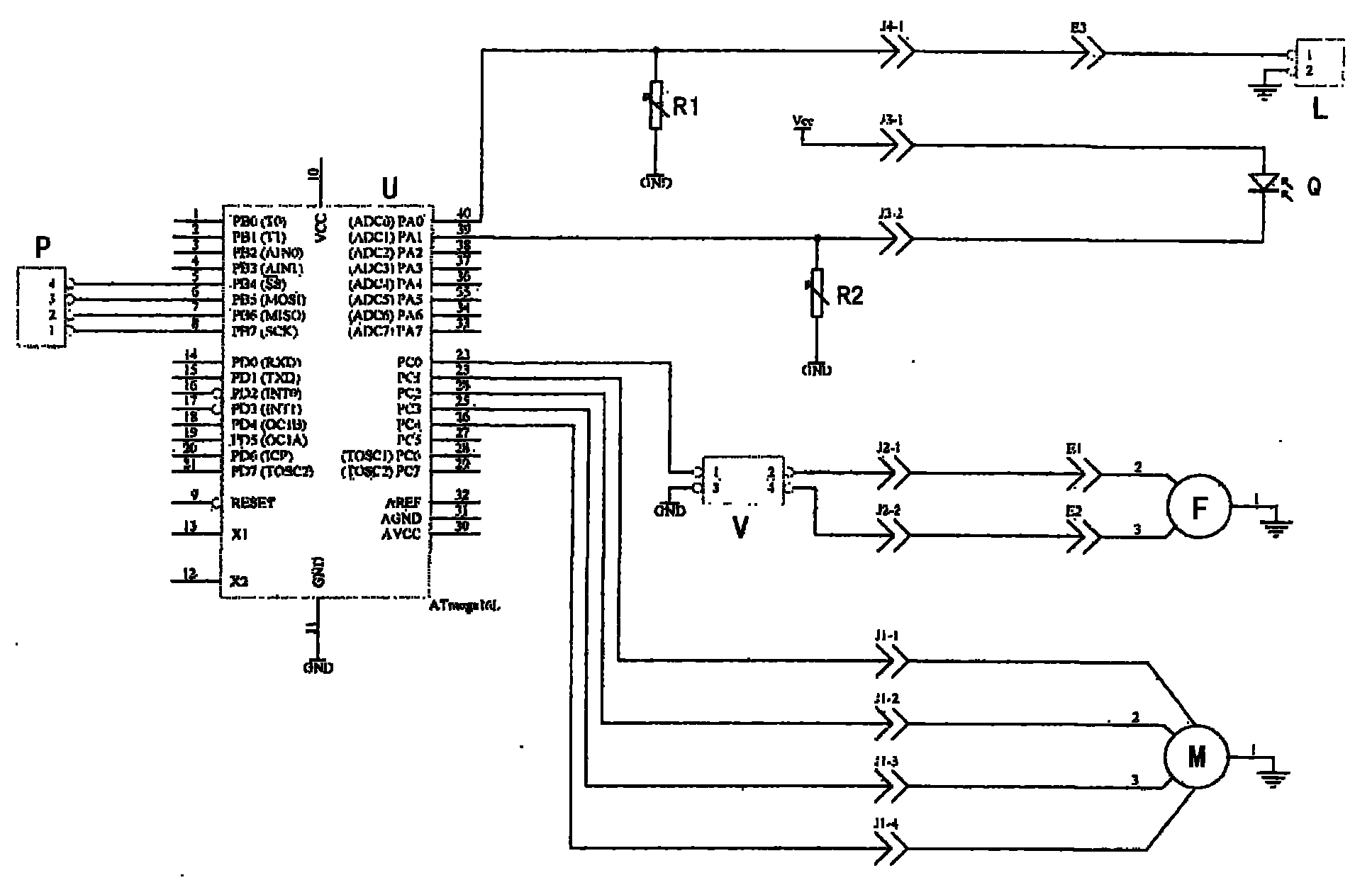
[0011] see figure 1 , the present invention comprises an infrared sensor Q, a single-chip microcomputer U, a variable frequency speed regulator V, a variable frequency speed regulating fan F, a stepping motor M and a damper, and the signal output terminal of the infrared sensor Q is connected with an input terminal PA1 of the single chip microcomputer U, and the PA1 end is connected with an input terminal PA1 of the single chip microcomputer U. A potentiometer R1 is connected between the grounds for adjusting the potential input to the microcontroller. One output terminal PC0 of the single-chip microcomputer U is connected to the frequency conversion speed regulating fan F through the frequency conversion speed regulator V, and the other output terminal PC1-PC4 of the single-chip microcomputer U is connected to the stepping motor M, and the stepping motor is used to drive the infrared burner the damper. An interface PA0 of the single-chip microcomputer U is connected with an ...


PUM


Abstract

The invention relates to an automatic control device of an infrared ray burner, which is characterized by comprising an infrared ray sensor, a singlechip, a variable-frequency governor, a variable-frequency speed regulating fan, a step motor and an air door, wherein the signal output end of the infrared ray sensor is connected with one end of the singlechip, one output end of the singlechip is connected with the variable-frequency speed regulating fan through the variable-frequency governor, the other output end of the singlechip is connected with the step motor, and the step motor drives the air door. The invention has the advantages of controlling the rotating speed of the fan or the opening of the air inlet air door by using the strength of infrared rays generated by infrared ray burning, maintaining the stability of the infrared ray burning, achieving the best energy-saving effect of the burner, saving great cost of manual adjustment, and bringing convenience for a user due to no need of maintenance.

Description

technical field [0001] The invention relates to an automatic control device for an infrared burner, which is mainly used in a combustion control system of a condensing wall-hung boiler to improve the combustion stability of the burner, and improve the thermal efficiency and use comfort of the wall-hung boiler. Background technique [0002] An existing condensing wall-hung boiler uses a negative pressure infrared combustion method to convert gas and heat energy, and this technology is very difficult. Since infrared burning ceramic plates are very sensitive to gas, air mixing ratio, gas pressure, atmospheric pressure, ambient temperature, etc., it is difficult to ensure the normal combustion of ceramic plates. There is not a relatively mature experience in the world that can be used for reference, especially in negative pressure combustion, and the stability needs to be improved. Experiments have shown that the mixing ratio of gas and air is the main factor affecting the comb...

Claims


Application Information

Patent Timeline
Patent Type & Authority Applications(China)
IPC IPC(8): F23N1/02
Inventor 郑曰和
Owner 郑乐斌
Why Eureka
Try Eureka