Demagnetization method and demagnetization circuit

A degaussing circuit and degaussing method technology, applied in the direction of circuits, magnetic objects, electrical components, etc., can solve the problems of complex AC power lines and difficult control of the degaussing process, and achieve control of the degaussing magnetic field size and degaussing time, flexible degaussing magnetic field size and Degaussing time, easy to achieve effect

Inactive Publication Date: 2010-09-01
湖南省联众科技有限公司
View PDF3 Cites 6 Cited by
  • Summary
  • Abstract
  • Description
  • Claims
  • Application Information

AI Technical Summary

Problems solved by technology

This method is advanced in technology and works well, but the program-controlled AC power circuit is complicated
[0007] Although the above-mentioned various degaussing methods can perform a certain degaussing effect, there are many disadvantages and shortcomings, which are difficult to overcome, and the degaussing process is not easy to control.

Method used


Image

  • Demagnetization method and demagnetization circuit
  • Demagnetization method and demagnetization circuit
  • Demagnetization method and demagnetization circuit

Examples


Embodiment 1

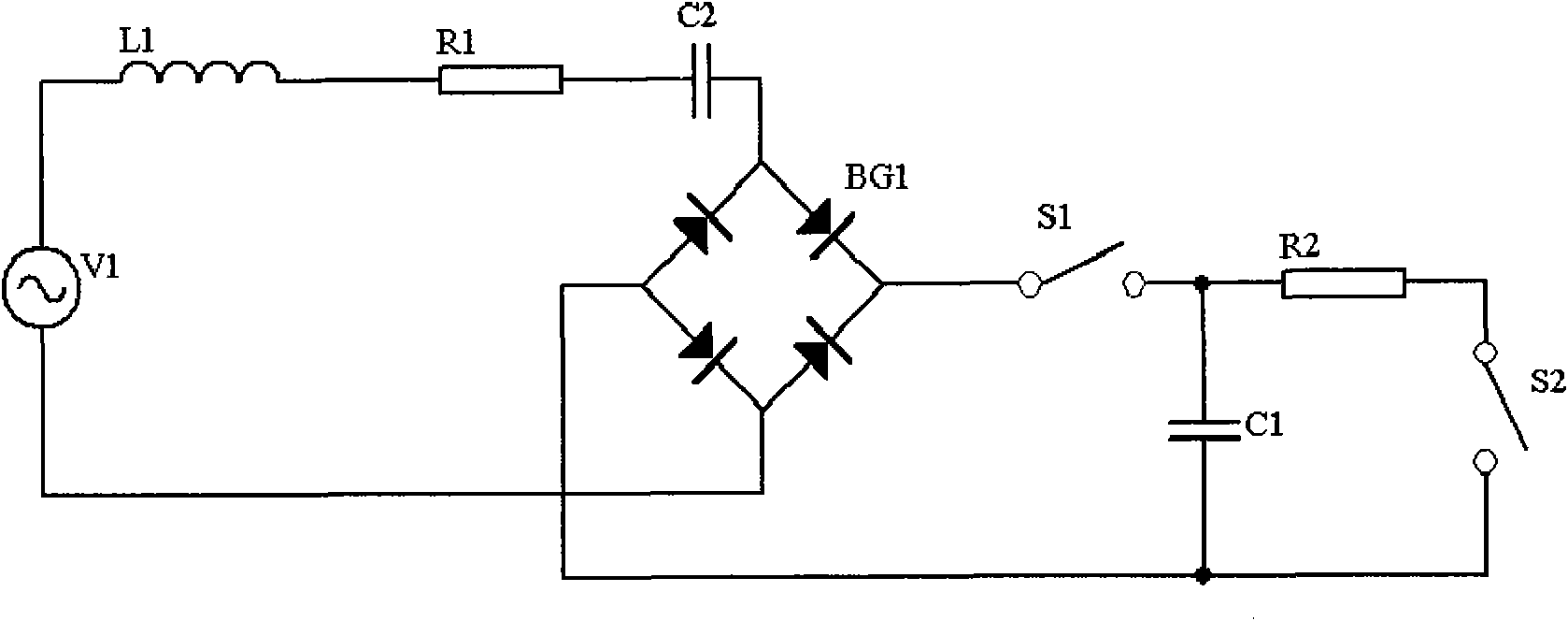
[0029] see figure 1 , The degaussing circuit of the present invention comprises an AC power supply V1, a magnetic field coil L1, a resistor R1, a resistor R2, a capacitor C1, a resonant capacitor C2, a diode bridge rectifier BG1, a switch S1 and a switch S2 connected together.

[0030] Wherein, the diode bridge rectifier stack BG1 may also be composed of four discrete diodes; the switch S1 and the switch S2 are mechanical switches, and may also be set as electronic switches.

[0031] The AC power supply V1 is 220V commercial power, one end is connected to the magnetic field coil L1, and the other end is connected to an AC terminal of the diode bridge rectifier BG1; the magnetic field coil is connected to the resistor R1 which acts as a current limiter, and the resistor R1 is connected to the resonant capacitor C2 to achieve resonance The capacitor C2 is then connected to another AC terminal of the diode bridge rectifier BG1, and the AC power supply V1, resistor R1, capacitor C...

Embodiment 2

[0044] see figure 2 , the difference from the first embodiment is that the current limiting resistor R1 is moved to the bridge arm of the diode bridge rectifier stack BG1, and four resistors R0 are respectively connected to the diodes, and all other components and positions remain unchanged.

[0045] In this way, the magnetic field coil L1 is directly connected to the resonant capacitor C2, and the current limiting function is realized by the four resistors R0 integrated into the diode bridge rectifier BG1. The degaussing principle and effect are the same as those in the first embodiment.

Embodiment 3

[0047] see image 3 , the difference from Example 1 is that the figure 1 The middle current-limiting resistor R1 is moved to the DC charging circuit, that is, the magnetic field coil L1 is directly connected to the resonant capacitor C2, one end of the current-limiting resistor R1 is connected to the DC terminal of the diode bridge rectifier BG1, and the other end is connected to the capacitor C1, and other components and positions remain constant.

[0048] Since the AC main circuit is connected to the DC charging circuit through the diode bridge rectifier BG1, and the current of the AC main circuit is controlled by the charging current of the DC charging circuit, moving the current limiting resistor R1 into the DC charging circuit can also play a role. To indirectly control the current of the AC main circuit, it has no effect on the principle and effect of degaussing.


PUM


Abstract

The invention discloses a demagnetization method and a demagnetization circuit. The change rule that charge current slowly decreases along with time and finally decreases to zero when a rectifying circuit charges a capacitor is used as the current change rule required for demagnetization in a magnetic field coil to achieve the purpose of demagnetizing magnetic materials. The demagnetization circuit comprises an AC main loop, a DC charge loop and a discharge loop, wherein the AC main loop is formed by connecting an AC power source, a magnetic field coil, a current limiting resistor, a resonant capacitor and an AC terminal of a diode bridge rectifier stack in series; the DC charge loop is formed by connecting a DC terminal of the diode bridge rectifier stack, two switches, a capacitor and a resistor; and one switch is used for controlling the DC charge loop, and the other switch is used for controlling the discharge loop. The invention has the advantages of novel method, skillful circuit structure, simple realization and good demagnetization effect, can achieve the purpose of repeated demagnetization, and can freely and flexibly regulate the demagnetization degree and the demagnetization time.

Description

technical field [0001] The invention relates to the field of degaussing by physical methods, in particular to a degaussing method and a degaussing circuit applied to a degaussing machine. Background technique [0002] Degaussing magnetic materials has troubled people for a long time, and there is no good solution. At present, the degaussing methods commonly used in the market mainly involve the following types: [0003] One is to charge the pulse capacitor, and then discharge the coil through the capacitor to form an attenuation oscillation and generate a demagnetization magnetic field. However, due to the limitation of the pulse capacitance, it is impossible to make the duration of the demagnetization magnetic field very long, which affects the effect of demagnetization. This method is generally only suitable for demagnetization or demagnetization of hard magnetic materials. [0004] The second method is to use a coil fixedly connected to the mains 220V or 380V to generat...

Claims


Application Information

Patent Timeline
Patent Type & Authority Applications(China)
IPC IPC(8): H01F13/00
Inventor 陈泽军
Owner 湖南省联众科技有限公司
Why Eureka
Try Eureka