
Laser triggered vacuum switch

A vacuum switch and laser technology, applied in the direction of electric switch, electronic switch, high-voltage/high-current switch, etc., can solve the problems of difficult manufacturing and processing, reduce production efficiency, affect work performance, etc., achieve convenient optical path calibration, prolong service life, The effect of improving productivity

Inactive Publication Date: 2010-09-01
HUAZHONG UNIV OF SCI & TECH
View PDF4 Cites 18 Cited by
  • Summary
  • Abstract
  • Description
  • Claims
  • Application Information

AI Technical Summary

Problems solved by technology

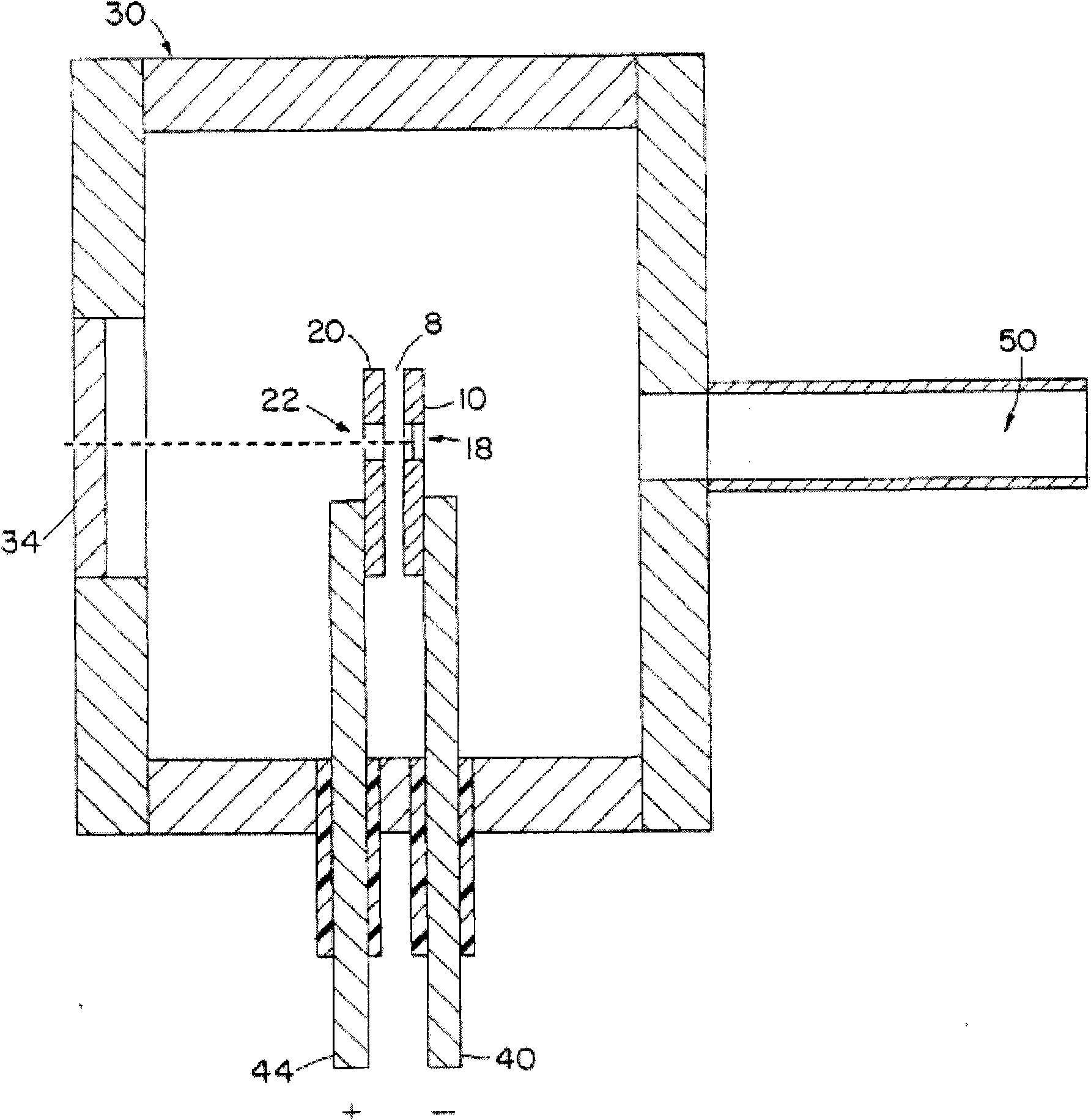
[0004] However, there are several problems in this laser-triggered vacuum switch: First, since the anode 20 and the cathode 10 are installed at one end of the electrode column 44 and 40 respectively, it is not easy to align the through hole 22, the target electrode 18 and the laser window 34, and the manufacturing process is difficult. , and reduced production efficiency
Second, when the switch is turned on, a relatively large electromotive force will be generated, and the anode 20 and the cathode 10 are both sheet-shaped, which are easily deformed, resulting in a change in the gap 8 between the anode 20 and the cathode 10, thereby causing work Voltage changes, affecting work performance
Third, because the distance between the electrode posts 44 and 40 is very close, they cannot withstand too high operating voltage, otherwise there is a possibility of breakdown

Method used


Image

  • Laser triggered vacuum switch
  • Laser triggered vacuum switch
  • Laser triggered vacuum switch

Examples


Embodiment Construction

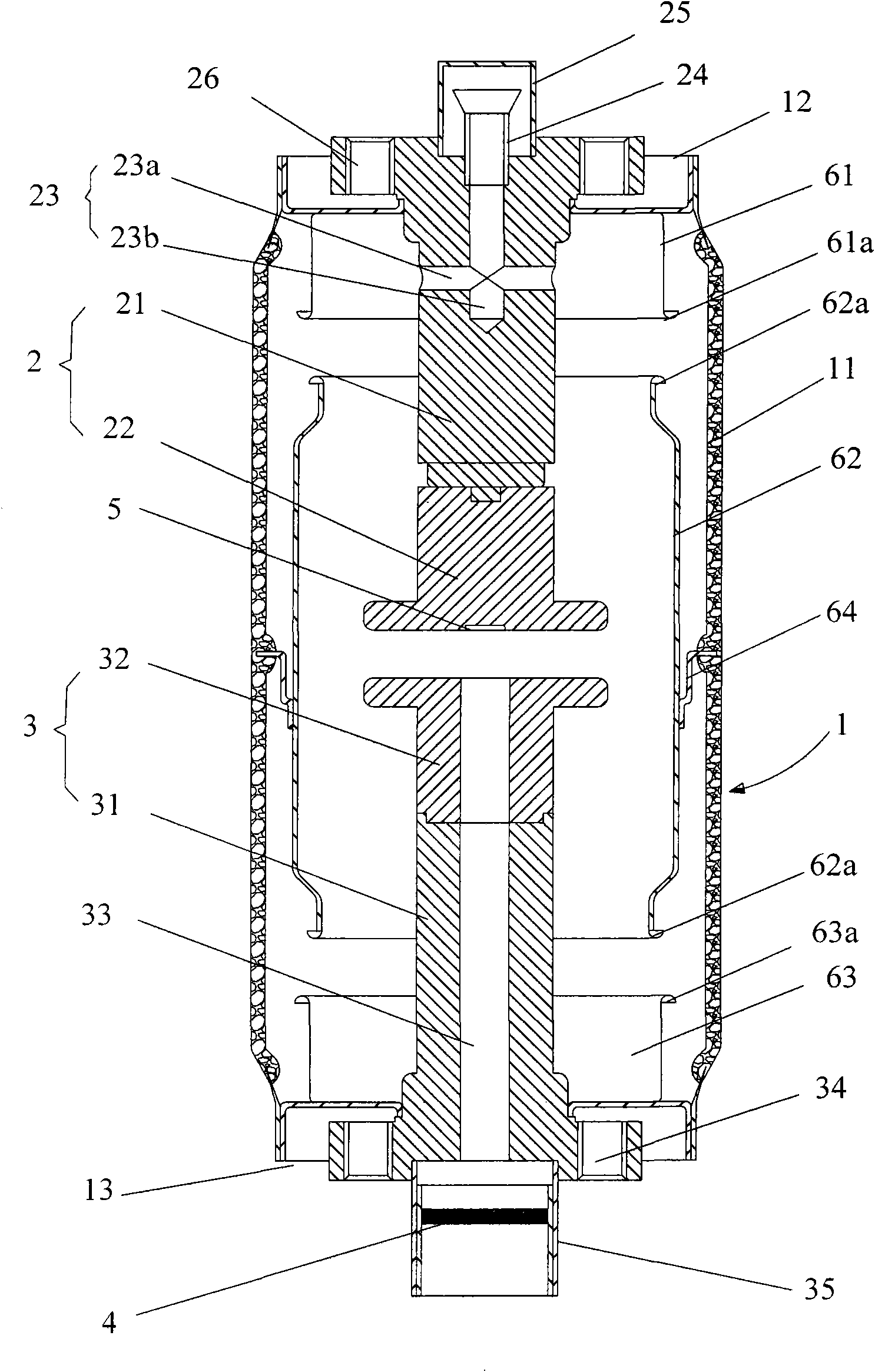
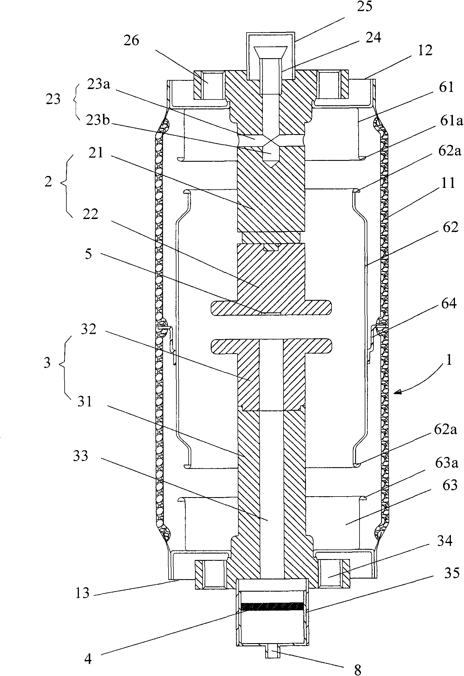
[0020] Embodiments of the present invention will now be described with reference to the drawings, in which like reference numerals represent like elements. As mentioned above, the present invention provides a laser trigger vacuum switch, which has simple structure, stable trigger performance, long service life and convenient processing.

[0021] The technical solutions of the embodiments of the present invention will be described in detail below in conjunction with the accompanying drawings. Such as figure 2 As shown, the laser-triggered vacuum switch of this embodiment includes an airtight casing 1 , a first electrode 2 and a second electrode 3 arranged on the airtight casing 1 , and a laser irradiation window 4 . The first electrode 2 and the second electrode 3 are respectively fixed at two ends of the airtight casing 1 .

[0022] Specifically, the airtight housing 1 includes an insulating shell 11, an upper end flange 12 and a lower end flange 13, and the upper end flang...


PUM

PropertyMeasurementUnit
Gapaaaaaaaaaa

Abstract

The invention discloses a laser triggered vacuum, which comprises an airtight shell, a first electrode, a second electrode and a laser irradiation window, wherein the first electrode and the second electrode are arranged on the airtight shell and are respectively fixed on both ends of the airtight shell, the second electrode is internally and axially provided with a through hole, one end face of the first electrode is provided with a target electrode opposite to the through hole, the laser irradiation window is positioned on the outer end of the second electrode, and the laser irradiation window, the through hole and the target electrode are positioned on same axis. The laser triggered vacuum switch has simple structure, stable triggering property, long service life and convenient processing.

Description

technical field [0001] The invention relates to an electronic switch device, in particular to a laser trigger vacuum switch. Background technique [0002] With the development of pulse power technology, the demand for high-power switching devices has greatly increased. The high-power switching device is the most important part of the pulse power supply. It must be able to work under the conditions of high voltage and high current, and it also requires fast response, high reliability, stable triggering and long life. Laser-triggered vacuum switch is a new type of switching device that combines laser technology with high-power pulse technology. It irradiates laser light on the target electrode to generate plasma vapor, and finally turns on the switch under the action of the main electrode voltage. Compared with other types of switches, the laser trigger vacuum switch has a wider operating voltage range and higher Coulomb power conduction characteristics, and its trigger syste...

Claims


Application Information

Patent Timeline
IPC IPC(8): H03K17/54
CPCH01T2/00H01H33/66H01H33/664H01H35/00
Inventor 何正浩刘俊翔朱璐许宇航张召亮
Owner HUAZHONG UNIV OF SCI & TECH
Learn More