Clock recovery device and method

A clock recovery and digital clock technology, which is applied in the direction of synchronization devices, electromagnetic wave transmission systems, digital transmission systems, etc., can solve the problem that digital clock recovery circuits cannot provide synchronous clocks, etc.

Inactive Publication Date: 2010-09-01
ZTE CORP +1
View PDF5 Cites 37 Cited by
  • Summary
  • Abstract
  • Description
  • Claims
  • Application Information

AI Technical Summary

Problems solved by technology

[0005] The technical problem to be solved by the present invention is to provide a clock recovery device and method to solve the problem that the digital clock recovery circuit cannot provide a synchronous clock, and to provide a synchronous clock while outputting synchronous samples

Method used


Image

  • Clock recovery device and method
  • Clock recovery device and method
  • Clock recovery device and method

Examples


Embodiment 1

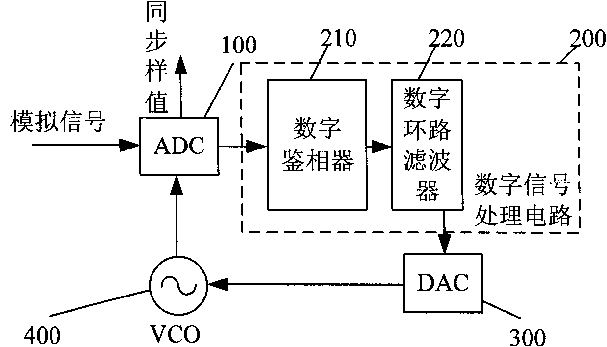
[0045] figure 2 Shown is the clock recovery device of this embodiment, including: analog-to-digital converter (ADC) 100, digital signal processing circuit 200, digital-to-analog converter (DAC) 300 and VCO400, wherein, ADC100, digital signal processing circuit 200, DAC300 It is connected with VCO400 in turn, and VCO400 is also connected with ADC100 to provide reference clock to ADC100;

[0046] The ADC100 converts the received analog signal to be processed into a digital signal, and sends the digital signal to the digital signal processing circuit 200; after synchronization is established, the ADC100 outputs a synchronous sampling value;

[0047] The digital signal processing part 200 includes: a digital phase detector 210 and a digital loop filter 220. The digital phase detector 210 receives the digital signal sent by the ADC100, performs phase detection processing on the digital signal, obtains a phase error signal, and converts the phase error signal Send to the loop filt...

Embodiment 2

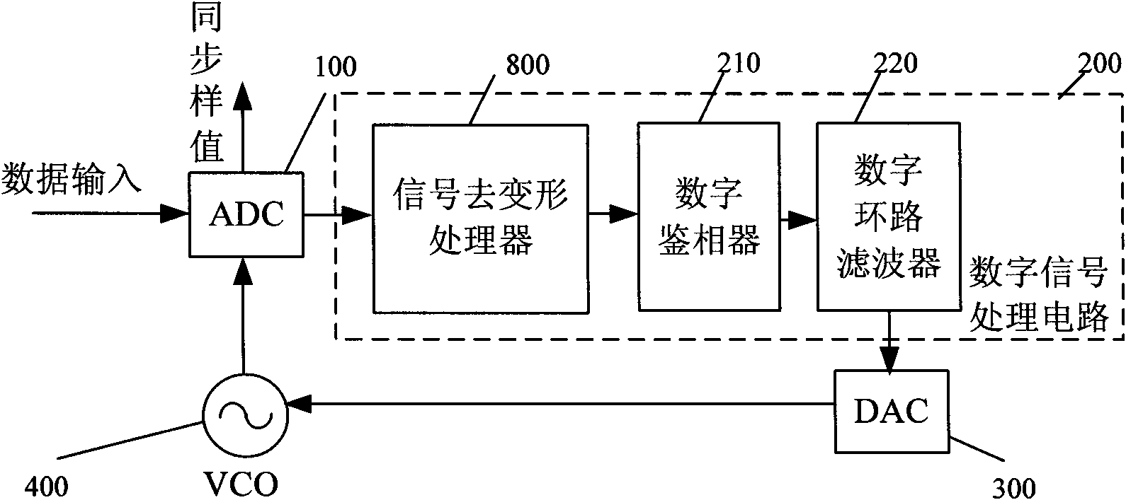
[0051] For a signal with serious distortion, a processing circuit can be added in the digital signal processing circuit 200 to weaken the distortion of the signal, and then perform clock recovery, such as image 3As shown, a signal de-distortion processor 800 is also connected between the ADC100 and the digital phase detector 210. After the digital signal converted by the ADC100 is processed by the signal de-distortion processor 800, a recoverable clock signal is obtained, and then the clock is processed. recover. The signal dewarping processor 800 may be an FIR filter for equalization.

Embodiment 3

[0053] For the case where the sampling rate of the ADC100 is different from the required sampling rate of the digital phase detector 210, such as Figure 4 As shown, a resampling circuit 900 can be added between the ADC100 and the digital phase detector 210, and the resampling circuit 900 resamples the digital signal converted by the ADC100 to obtain a digital signal with a sampling rate required by the digital phase detector 210, and then Then perform clock recovery.


PUM


Abstract

The invention discloses a clock recovery device and a clock recovery method. The clock recovery device comprises an analog-to-digital converter, a digital signal processing circuit, a digital-to-analog converter and a voltage-controlled oscillator which are connected in turn, wherein the voltage-controlled oscillator is connected with the analog-to-digital converter; the analog-to-digital converter is used for converting received analog signals into digital signals, and sending the digital signals to the digital signal processing circuit; the digital signal processing circuit is used for carrying out phase demodulation and filtering processing on the received digital signals so as to obtain digital clock error signals, and sending the digital clock error signals to the digital-to-analog converter; the digital-to-analog converter is used for converting the received digital clock error signals into control voltage signals, and sending the control voltage signals to the voltage-controlled oscillator; and the voltage-controlled oscillator is used for generating a synchronous clock according to the received control voltage signals, and outputting the synchronous clock to the analog-to-digital converter. The invention can provide a reference clock for chips in a digital circuit.

Description

technical field [0001] The invention relates to a digital signal receiver in a communication system, in particular to a clock recovery device and method. Background technique [0002] In the signal receiver of the communication system, it is necessary to solve the problem that the sampling point is not synchronized with the signal at the sending end. Only by solving the synchronization problem can the correct signal be obtained. Clock recovery is to realize the synchronization between the two. [0003] Such as figure 1 As shown, a digital clock recovery circuit usually includes an ADC (Analog-to-Digital Converter), an interpolation filter, a digital phase detector, a digital loop filter, and a numerically controlled oscillator (NCO) connected in sequence, and the signal of the NCO is fed back to the interpolation filter. [0004] The above-mentioned digital clock recovery circuit can only obtain a sample sequence that is synchronized with the signal at the transmitting end...

Claims


Application Information

Patent Timeline
Patent Type & Authority Applications(China)
IPC IPC(8): H04L7/033H04L27/227H04B10/158
CPCH04L27/227H04L7/0334H04L7/0054
Inventor 周伟勤易鸿陈雪樊洋洋周娴
Owner ZTE CORP
Why Eureka
Try Eureka