

Illuminating unit
A lighting unit and substrate technology, applied in lighting applications, household lighting, lighting devices, etc., can solve the problems of unsuitable lighting applications, narrow lighting range of lighting units, etc., and achieve the effect of high illuminance
- Summary
- Abstract
- Description
- Claims
- Application Information
AI Technical Summary
Problems solved by technology
Method used
Image

Examples
Embodiment approach 1
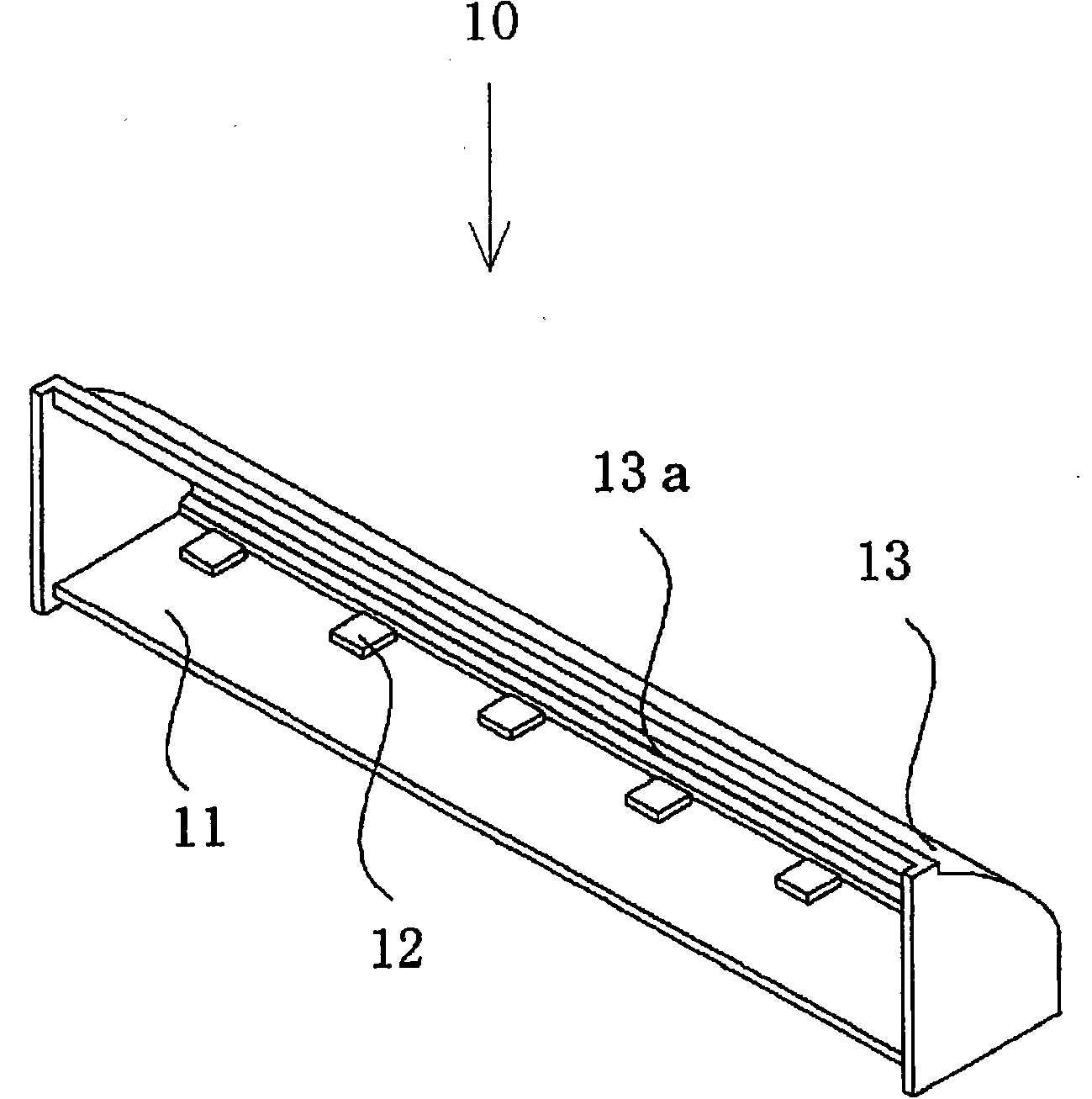
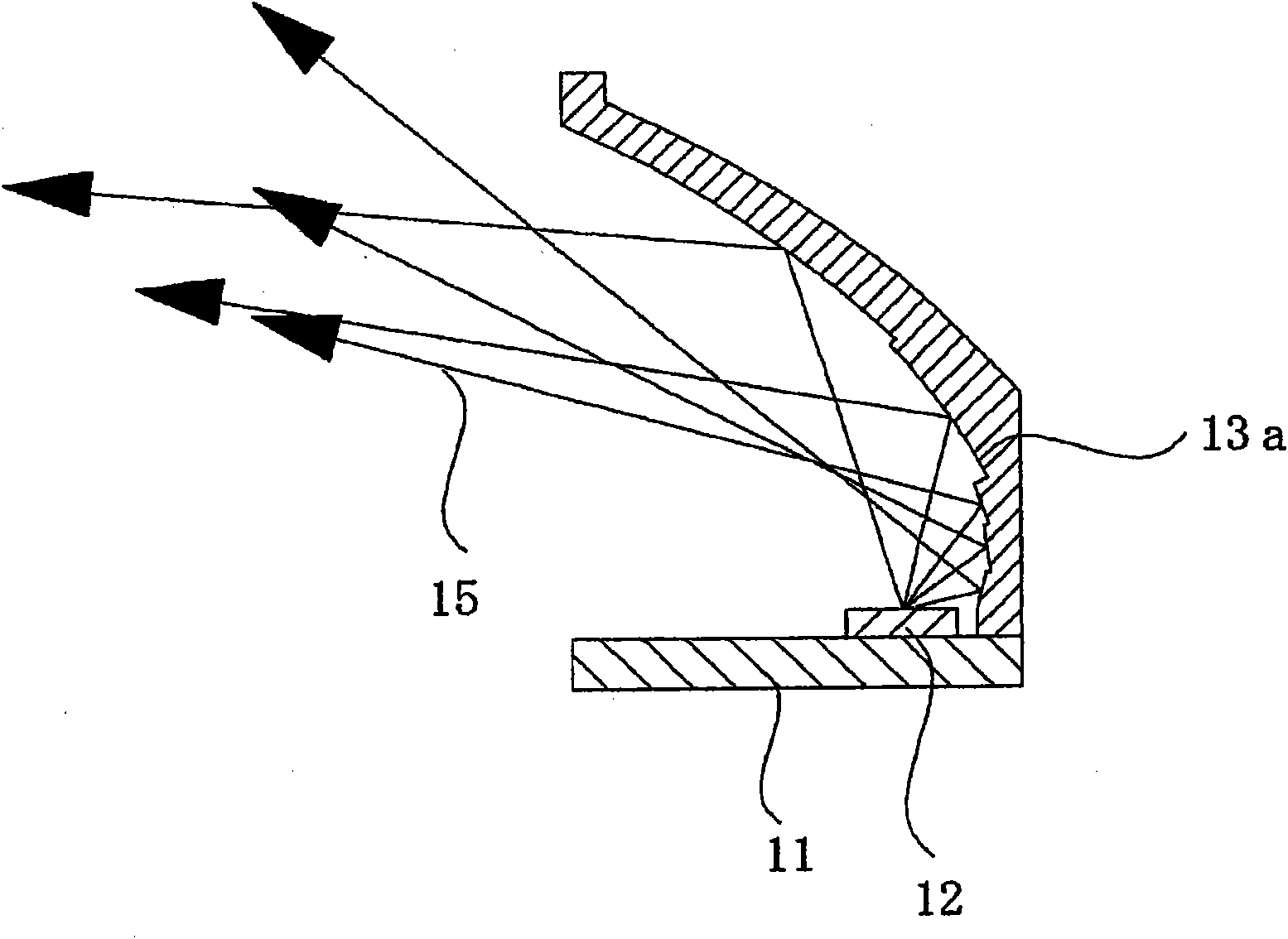
[0035] Figure 1A It is a schematic perspective view seen from the top side, Figure 1B is a schematic cross-sectional view of the substrate width direction, as in the Figure 1A , 1B As shown, the lighting unit 10 of this embodiment is mainly composed of a long substrate 11, a plurality of semiconductor light sources 12 arranged in a row along the length direction on the substrate, and a light source arranged along one long side of the substrate. The light reflector 13 is constituted.
[0036] The substrate 11 is formed in a shape extending in the longitudinal direction, and a plurality of semiconductor light sources 12 are arranged in a row on the upper surface side of the substrate 11 in the longitudinal direction. The substrate 11 is a substrate implemented by a known method in this field. The substrate 11 has wiring and a wiring pattern for making the semiconductor light source 12 emit light on the upper surface and the bottom surface facing the upper surface, and variou...
Embodiment approach 2
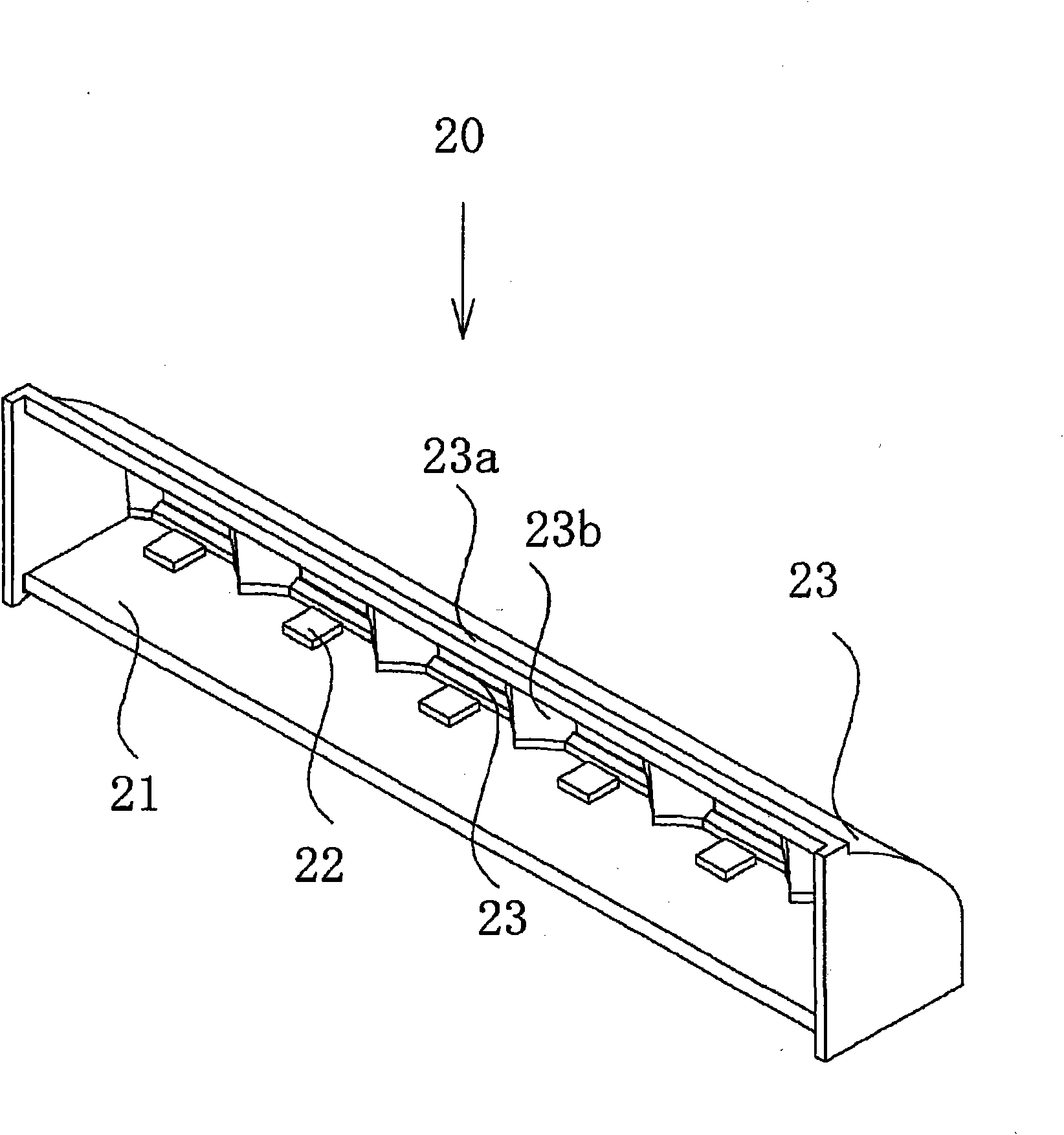
[0047] The lighting unit 20 of the second embodiment is as figure 2 As shown, the multilayer reflector 23a is divided among the plurality of semiconductor light sources 22, and the side reflector 23b is provided in the divided part, and its structure is substantially the same as that of the first embodiment.
[0048]In this embodiment, a plurality of multilayer reflectors 23a and a plurality of semiconductor light sources 22 are arranged in pairs. Thereby, the light from each semiconductor light source 22 can be efficiently extracted to the outside by the multilayer reflector 23a, and the utilization efficiency of light can be improved. Moreover, the light reflection body of this embodiment has the side reflector 23b which protrudes between each semiconductor light source 22 from between each multilayer reflector 23a. Thus, by using a side reflector protruding between the plurality of semiconductor light sources, non-utilized light directed in the longitudinal direction of t...
Embodiment approach 3
[0050] In the lighting device 100 according to Embodiment 3, two sets of lighting units 30 are arranged in the longitudinal direction of the substrate 31 and held in one casing 101. The lighting unit 30 has a metal plate 34, a substrate 31 on which a semiconductor light source 32 is mounted, Light reflector 33 .
[0051] The metal plate 34 is made of, for example, a metal material with high thermal conductivity such as aluminum, copper, iron, or stainless steel. In addition, the shape of the metal plate is not limited to a plate shape, but a heat sink shape with fins added thereto, or a shape that becomes a part of the structural configuration of the case may be added.
[0052] In Embodiment 3, the same devices as in Embodiments 1 and 2 can be used for the semiconductor light source 32 and the substrate 31 on which the light source is mounted. The light reflector has substantially the same structure as the light reflector used in Embodiment 2 except that the back surface has ...
PUM
 Abstract
Description
Claims
Application Information