Hemodialysis system

A technology of hemodialysis and dialysate, applied in the field of hemodialysis system, can solve the problems of large degassing negative pressure, fast gear wear, no circulation, etc., and achieve the effects of easy speed control, good degassing effect and low operating noise.

Active Publication Date: 2010-09-15
SWS HEMODIALYSIS CARE CO LTD
View PDF5 Cites 11 Cited by
  • Summary
  • Abstract
  • Description
  • Claims
  • Application Information

AI Technical Summary

Problems solved by technology

[0003] 1) The degassing gear pump is not only used for degassing, but also pushes the diaphragm of the balance chamber. It is difficult to control the speed of the gear pump, the operating pressure of the water circuit of the whole machine is high, and the service life of the water circuit components is short
[0004] 2) There is no circulation during the

Method used


Image

  • Hemodialysis system
  • Hemodialysis system

Examples


Embodiment Construction

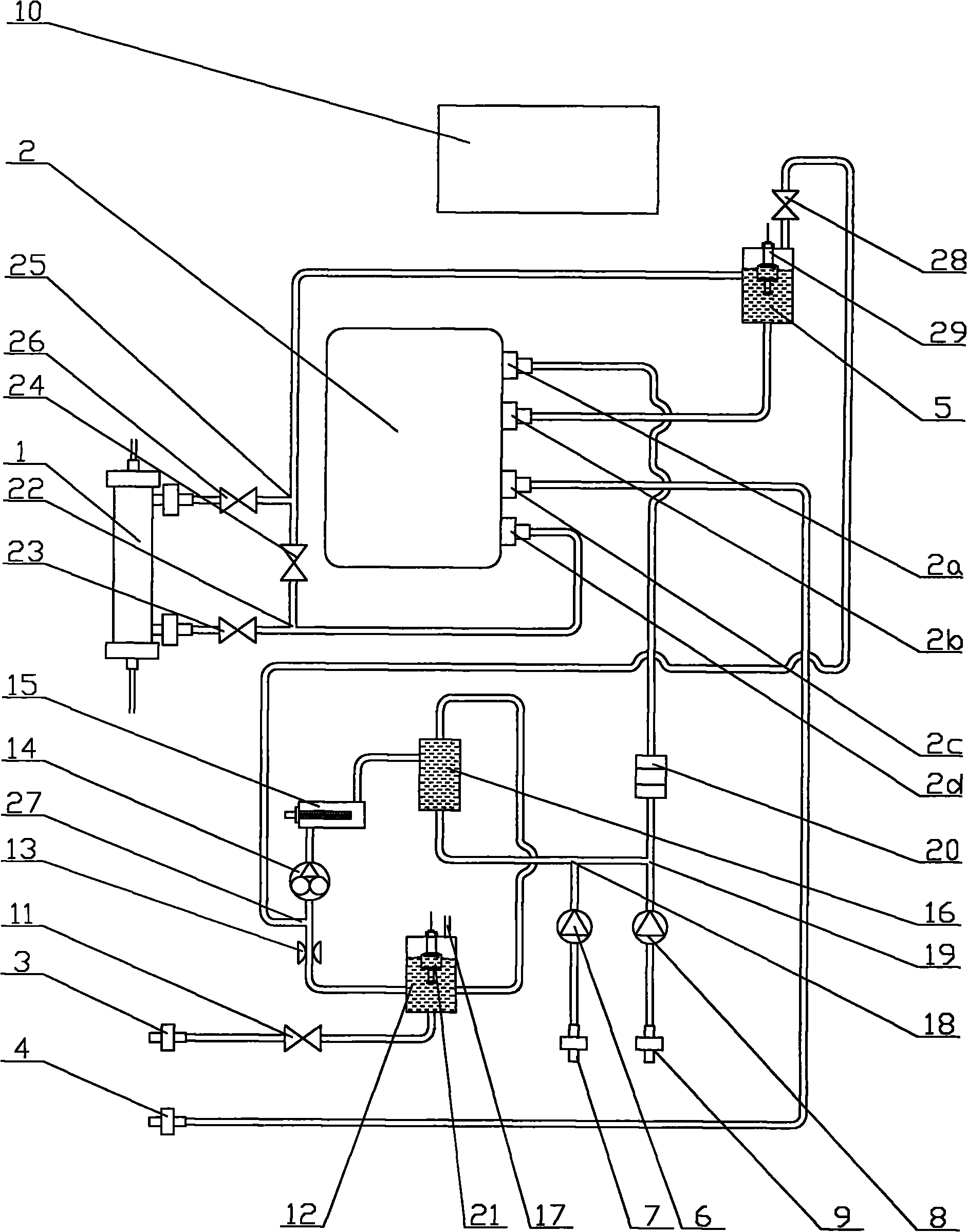
[0023] Below in conjunction with accompanying drawing and embodiment, the present invention will be further described:

[0024] like figure 1 As shown, the water supply end joint 3 is connected to one end of the pipeline, the other end of the pipeline is connected to the inlet of the first solenoid valve 11, and the outlet of the first solenoid valve 11 is connected to the liquid inlet joint at the bottom of the water inlet tank 12 through the pipeline connect. The liquid outlet joint in the middle of the water inlet tank 12 is connected to the inlet of the throttling member 13 through a pipeline. The throttling member 13 is in the prior art, and its structure is not repeated here. The outlet of the throttling member 13 is connected to the fifth The first end of the three-way pipe 27 is connected, the second end of the fifth three-way pipe 27 is connected with the inlet of the first gear pump 14 , and the third end of the fifth three-way pipe 27 is connected with the outlet o...


PUM


Abstract

The invention relates to a hemodialysis system. In the hemodialysis system, a water supply end joint is connected with a liquid inlet joint of a water inlet pot, and a liquid outlet joint of the water inlet pot is connected with an inlet of a throttling member; the outlet of the throttling member is connected with the inlet of a first gear pump, the outlet of the first gear pump is connected with a heater in series and then connected with a liquid inlet joint of a separation pot, and a first liquid outlet joint of the separation pot is connected with a backflow joint of the water inlet pot; a second liquid outlet joint of the separation pot is connected with a first end of a first three-way pipe, and a second end of the first three-way pipe is connected with a concentrated solution pump A in series and then connected with a concentrated solution joint A; a third end of the first three-way pipe is connected with a first end of a second three-way pipe; a second end of the second three-way pipe is connected with a concentrated solution pump B in series and then connected with a concentrated solution joint B; and a third end of the second three-way pipe is connected with an electrical conductance monitor in series and then connected with a dialysate inlet joint of a capacity balancing and ultrafiltering device. In the hemodialysis system, the rotating speed of the gear pump is easy to control, and the operation noise is lower; the waterway operation pressure of the whole system is lower; and the service life of waterway parts is longer.

Description

technical field [0001] The present invention relates to a medical device, in particular to a hemodialysis system. Background technique [0002] Hemodialysis (HD) is one of the most widely used treatments in the field of blood purification. Hemodialysis uses the principles of dispersion and ultrafiltration to introduce the patient's blood and dialysate into the dialyzer at the same time, and flow in opposite directions on both sides of the dialysis membrane. The diffusion effect achieves the concentration balance on both sides, removes metabolic wastes and excess water in the human body, and at the same time replenishes the needed substances and corrects electrolyte and acid-base balance disorders. Existing hemodialysis equipment generally consists of hemodialyzer, pipeline, volume balance and ultrafiltration device, A concentrate pump, A concentrate connector, B concentrate pump, B concentrate connector, water supply end connector, drain end connector, The waste liquid tan...

Claims


Application Information

Patent Timeline
IPC IPC(8): A61M1/14
CPCA61M1/1656A61M1/1658A61M1/1668
Inventor 高光勇沈洪甘华任应祥李昔华刘智勇罗自宜
Owner SWS HEMODIALYSIS CARE CO LTD
Why Eureka
Try Eureka