CMOS (Complementary Metal-Oxide-Semiconductor Transistor) rectifier

A technology of rectifier and rectifier module, applied in the field of rectifier, can solve problems such as increasing chip cost, and achieve the effect of reducing cost

Inactive Publication Date: 2010-09-15
NATIONZ TECH INC
View PDF0 Cites 6 Cited by
  • Summary
  • Abstract
  • Description
  • Claims
  • Application Information

AI Technical Summary

Problems solved by technology

Rectifiers using Schottky diodes as rectifiers are used in passive RFID tag chips requir

Method used


Image

  • CMOS (Complementary Metal-Oxide-Semiconductor Transistor) rectifier
  • CMOS (Complementary Metal-Oxide-Semiconductor Transistor) rectifier
  • CMOS (Complementary Metal-Oxide-Semiconductor Transistor) rectifier

Examples


Embodiment 1

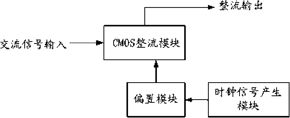
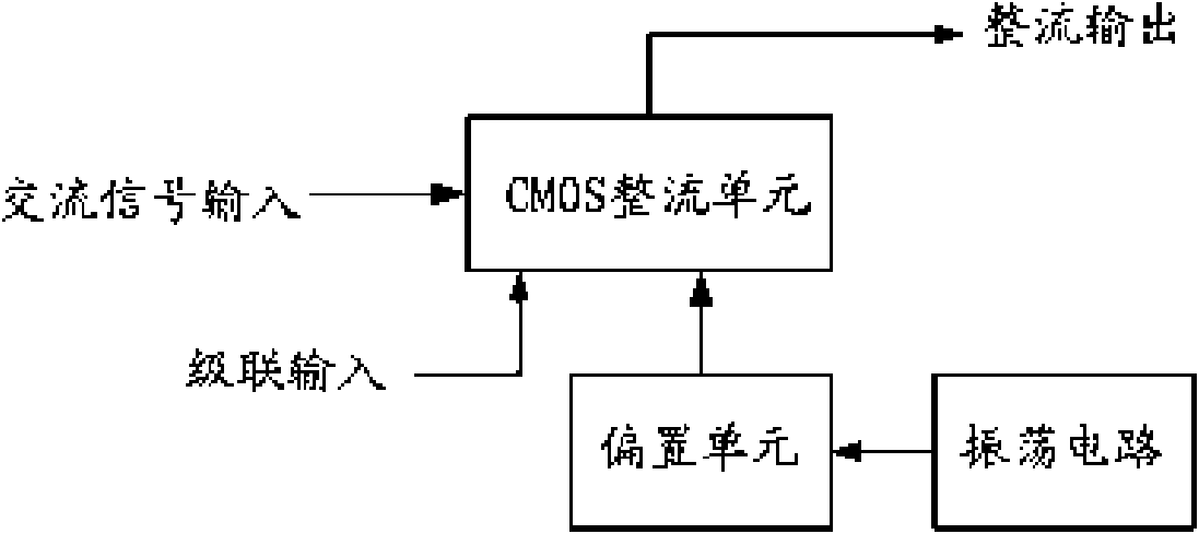
[0031] Such as figure 2 Shown is a structural block diagram of Embodiment 1 of the CMOS rectifier of the present invention. The rectifier may include: a CMOS rectifier unit, which uses a CMOS transistor as a rectifier device to convert an AC signal into a DC signal, inputs an AC signal through its input terminal, and outputs a DC signal at its output terminal after rectification. The rectifier unit also has a cascaded input terminal , used to connect the lower-level CMOS rectifier unit, so that a cascaded rectifier can be realized; the bias unit is used to provide a DC bias voltage for the CMOS transistor in the CMOS rectifier unit, and the bias unit is composed of a switched capacitor circuit, and The connection of CMOS tubes is realized; the oscillation circuit is used to provide two-phase non-overlapping clock signals for the bias unit.

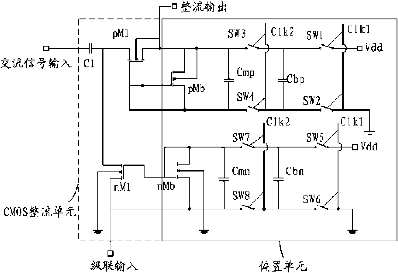
[0032] image 3 It is a circuit diagram of a CMOS rectification unit and a bias unit.

[0033] Wherein, the CMOS rectification unit m...

Embodiment 2

[0037] Figure 4 It is a block diagram of the second embodiment of the CMOS rectifier of the present invention, which is a three-stage cascaded CMOS rectifier, wherein the cascaded input end of the first CMOS rectifier unit is grounded, and the first bias unit provides DC bias for it voltage; the cascade input end of the second CMOS rectifier unit is connected to the output end of the first CMOS rectifier unit, and the second bias unit provides a DC bias voltage for it; the cascade input end of the third CMOS rectifier unit is connected to the second CMOS rectifier unit The output terminal of the rectifying unit is connected, and the third bias unit provides a DC bias voltage for it; the output terminal of the third bias unit is the output terminal of the three-stage cascaded CMOS rectifier, the first CMOS rectifying unit, the second CMOS The junction of the rectifier unit and the AC signal input end of the third CMOS rectifier unit is the AC signal input end of the CMOS recti...

Embodiment 3

[0040] Such as Figure 5 As shown, the CMOS rectifier is used in radio frequency power detection, and a voltage detection circuit is connected to the input end of the CMOS rectifier to realize radio frequency power detection.


PUM


Abstract

The invention relates to a rectifier used in a non-contact tag chip, in particular to a CMOS (Complementary Metal-Oxide-Semiconductor Transistor) rectifier. The CMOS rectifier comprises a CMOS rectifier module, a biasing module and a clock signal generation module. The CMOS rectifier can be realized by adopting a common CMOS tube in a standard CMOS process, is suitable for a passive radio frequency identification tag chip, avoids using special appliances such as a Schottky diode and the like and depending on a certain special process, and can effectively lower the cost of the passive radio frequency identification tag chip.

Description

technical field [0001] The invention relates to a rectifier in a non-contact tag chip, in particular to a complementary metal oxide semiconductor (CMOS) rectifier. Background technique [0002] A rectifier is a rectifying device, simply put, a device that converts alternating current (AC) into direct current (DC). In common rectifiers, Schottky diodes are used as rectifiers. [0003] Radio Frequency Identification (RFID, Radio Frequency Identification), also known as electronic tags, is an automatic identification technology that began to emerge in the 1990s. It uses radio frequency signals to achieve contactless information transmission through spatial coupling (alternating magnetic fields or electromagnetic fields). And through the transmitted information to achieve the purpose of identification technology. In the passive RFID tag, the high-frequency signal generated by its reader is converted into the DC energy required for its work through a rectifier. The use of a re...

Claims


Application Information

Patent Timeline
IPC IPC(8): H02M7/02H02M7/12
Inventor 孙迎彤周盛华
Owner NATIONZ TECH INC
Why Eureka
Try Eureka