Tension leveler for continuous caster

A technology of a tension leveler and a connecting pipe, applied in the field of steel casting, can solve the problems of inconvenient maintenance, reduced water pressure, no water cooling, etc., and achieve the effects of improving the cooling effect, enhancing the cooling effect, and reducing the difficulty of hoisting.

Inactive Publication Date: 2010-09-22
CONTINUOUS CASTING TECH ENG OF CHINA
View PDF0 Cites 7 Cited by
  • Summary
  • Abstract
  • Description
  • Claims
  • Application Information

AI Technical Summary

Problems solved by technology

[0005] In the existing tension leveling machine device, the main water inlet and return ports are set on the main water inlet and return pipes, the diameter of the main water inlet and return pipes is limited, the amount of water flowing into the water distribution device is limited, the fluidity of the cooling water is weak, and the cooling effect on the functional components is not good. it is good
All the water inlets are set on the main water inlet pipe, because the front and rear of the installation positions are different, and the water pressure is different, so that the front parts can still be cooled, and the water pressure of the rear parts is obviously reduced or even without water cooling. Uneven cooling of parts
[0006] The structure of the stainless steel water-cooled piping is complicated when connected inside the device, and it is difficult to find the fault point
In order to reduce leakage points, each pipe adopts welded elbows and tees, which brings inconvenience to maintenance
[0007] see Figure 5 , Image 6 , the stainless steel main water inlet and return pipes are located outside the tension leveler. In order to ensure that the external water pipes do not collide, it is necessary to increase the distance between the body of the tension leveler, which increases the difficulty of lifting

Method used


Image

  • Tension leveler for continuous caster
  • Tension leveler for continuous caster
  • Tension leveler for continuous caster

Examples


Embodiment 1

[0038] Embodiment one, see Figure 7 to Figure 9 , a water distribution device for a tension leveling machine, comprising a first column 1, a second column 2, a third column 3 and a fourth column 4, and various functional components arranged in a rectangular space surrounded by four columns, the four columns There are connecting pipes inside, and the connecting pipes are connected to each other; the first column 1 is provided with a general water inlet 5, the first column 1 and the second column 2 are water inlet columns, and the water inlet columns are connected. The second column 2 is connected through the water pipes 7 and 8; the third column 3 is provided with a total return water port 6, the third column 3 and the fourth column 4 are return water columns, and the return water columns are connected. The third column 3 and the fourth column The column 4 is connected through the water pipes 9 and 10; the water inlet column and the return water column are connected through th...

Embodiment 2

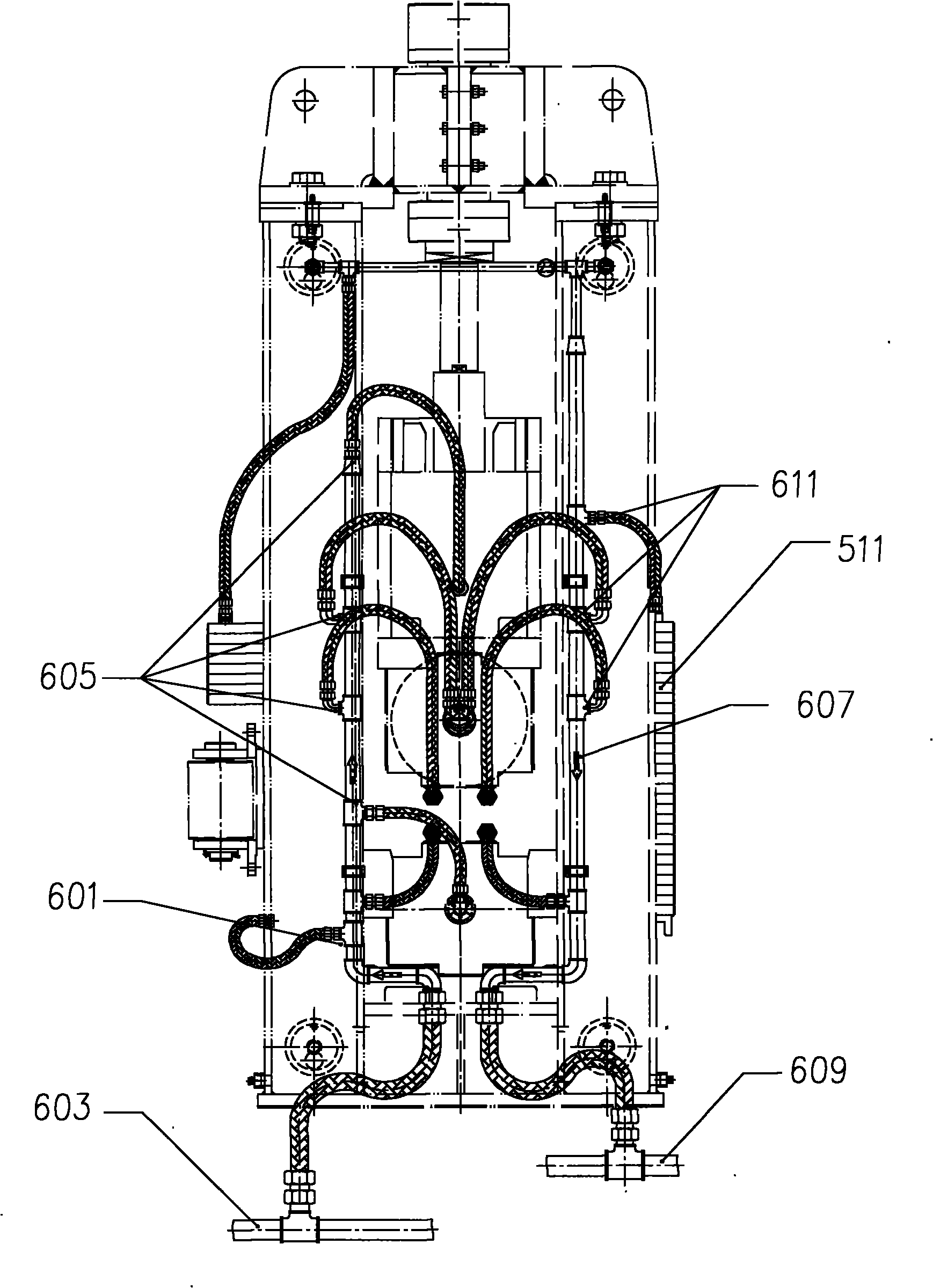
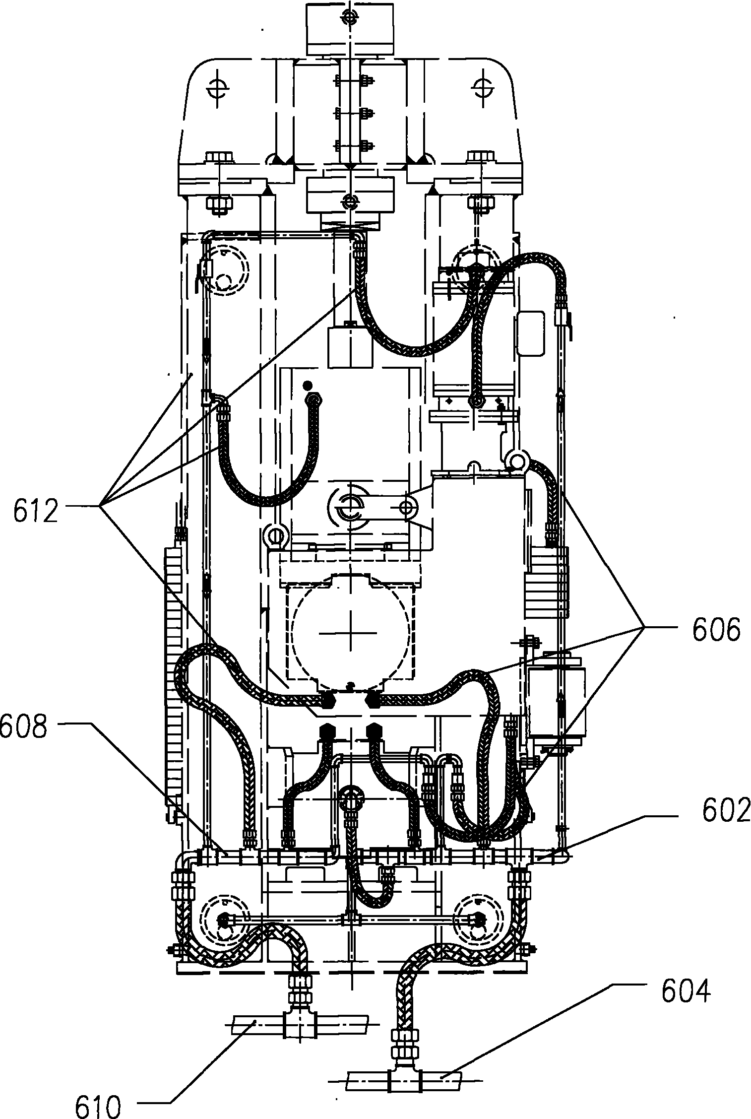
[0057] In the second embodiment, in the cooling device of the tension leveling machine, each water inlet and outlet are connected to each functional component through metal hoses, and the columns are connected through metal hoses. Determine the amount of cooling water required by each component by calculation, reasonably arrange the diameter and position of the inlet and outlet of each column, drill holes on each column and weld the pipe socket with the corresponding diameter; the inlet and outlet of all components to be cooled are respectively used The metal hose communicates with the pipe socket on the corresponding column. A regulating valve is installed on the metal hose to adjust the water flow online according to the working conditions of the tension leveler to ensure sufficient cooling of each functional component.

[0058] The water inlets and outlets are directly connected to the water inlet and return columns through metal hoses, which ensures the cooling effect of e...

Embodiment 3

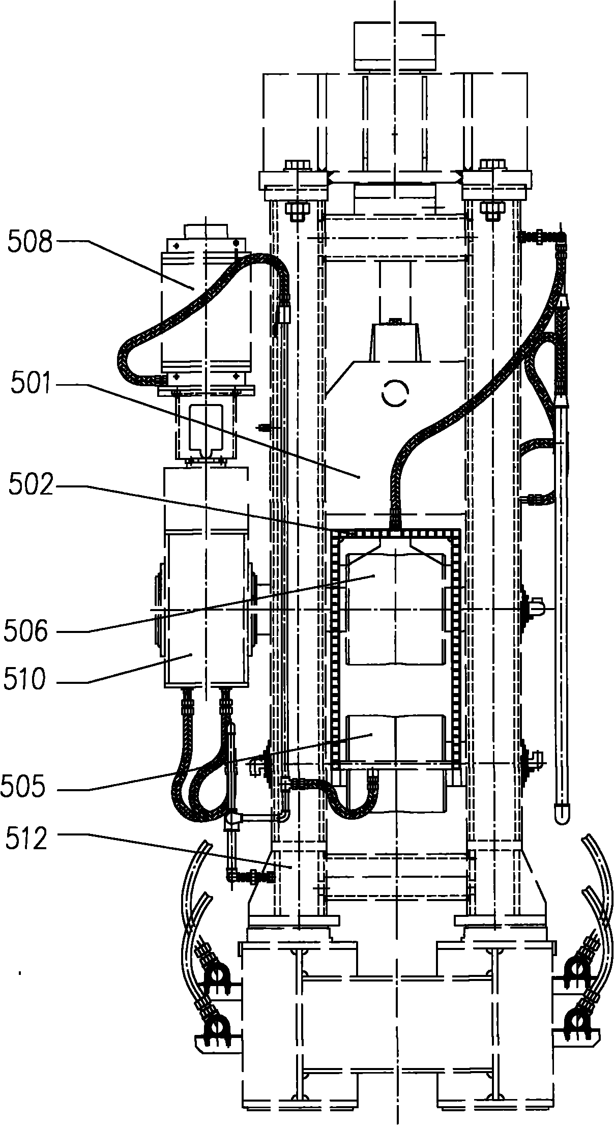
[0059] Embodiment 3, in the tension leveling machine device, an exhaust valve is provided at the connection between the water inlet column 1, 2 and the return water column 3, 4. Wherein, an exhaust valve 512 is provided at the connection between the first column 1 and the second column 2 , and an exhaust valve 513 is provided at the connection between the third column 3 and the fourth column 4 . see Figure 10 , Exhaust valves 512 and 513 are respectively arranged on the water pipe 8 and the water pipe 9 .

[0060] During the process of cooling the components with cooling water, a large amount of water vapor will be generated, and a large amount of water vapor will stay in the cooling water pipe, which will cause poor water flow and is not conducive to the flow of cooling water. There is an exhaust valve to discharge a large amount of water vapor from the device in time, which helps to enhance the fluidity of cooling water.

[0061] In the device of the present invention, th...


PUM


Abstract

The embodiment of the invention discloses a tension leveler for a continuous caster, which comprises a first upright post, a second upright post, a third upright post, a fourth upright post and functional components. The functional components are arranged in a rectangular space enclosed by four upright posts; communicating pipes are arranged in the four upright posts respectively and communicated with one another; the first upright post is provided with a main water inlet; the third upright post is provided with a main water return port; the first upright post and the second upright post are provided with a plurality of water intakes; the third upright post and the fourth upright post are provided with a plurality of water outlets; and the water intakes and the water outlets are communicated with the components through water pipes. The water inlet and the water return port are directly arranged on a water inlet upright post and a water return upright post, so water inlet and water return drift diameters are increased, cooling water flow rate is increased, and the mobility of cooling water is accelerated. The functional components are directly connected with the water inlet upright post and the water return upright post through the water pipes, so the flow rates of water flowing through the function components are ensured, the problem of non-uniform cooling caused by the lowered back end water pressure is solved, and a fault point is easy to check when the device fails.

Description

technical field [0001] The invention relates to the field of iron and steel casting, in particular to a tension leveler for continuous casting machines. Background technique [0002] In the field of iron and steel smelting, continuous casting machines are used to cast molten iron and steel from blast furnaces into fixed shapes. The pouring mechanism of the continuous casting machine pours the molten steel into the crystallizer. Under the joint action of the crystallizer, the sector section and the secondary cooling section, the molten steel is solidified from a liquid state into a billet with a fixed shape. Under the action of straightening, a slab that meets the requirements is formed. The hot billet keeps the tension leveler in a high temperature environment all the time. To ensure the normal operation of the tension leveler, it is necessary to cool the functional components in the tension leveler. [0003] see Figure 1 to Figure 3 , the existing tension leveling machin...

Claims


Application Information

Patent Timeline
Patent Type & Authority Applications(China)
IPC IPC(8): B22D11/12
Inventor 申汉芳周干水
Owner CONTINUOUS CASTING TECH ENG OF CHINA
Why Eureka
Try Eureka