Servo hydraulic transmission mechanism

A technology of servo hydraulic cylinders and hydraulic valves, which is applied to servo motor components, fluid pressure actuators, mechanical equipment, etc., can solve the problems of complex structure, complicated interlocking devices, and high prices, so as to avoid hidden dangers of mechanical failure and meet Long travel, economical and reliable results

Inactive Publication Date: 2010-09-22
宋家骏
View PDF1 Cites 15 Cited by
  • Summary
  • Abstract
  • Description
  • Claims
  • Application Information

AI Technical Summary

Problems solved by technology

[0002] The existing plate-frame and box-type filter presses generally use hydraulic cylinders to compress the filter plate, in which the pressure relay is used to control the pressing force, and the travel switch is used to control the return stroke. The control sensitivity or precision is relatively poor, and the control function is not perfect.
In addition, multi-cylinder pressing lacks effective synchronous technical measures, and serious mechanical failures have occurred
U.S. Patent US6099725 uses two hydraulic cylinders arra

Method used


Image

  • Servo hydraulic transmission mechanism
  • Servo hydraulic transmission mechanism
  • Servo hydraulic transmission mechanism

Examples


Example Embodiment

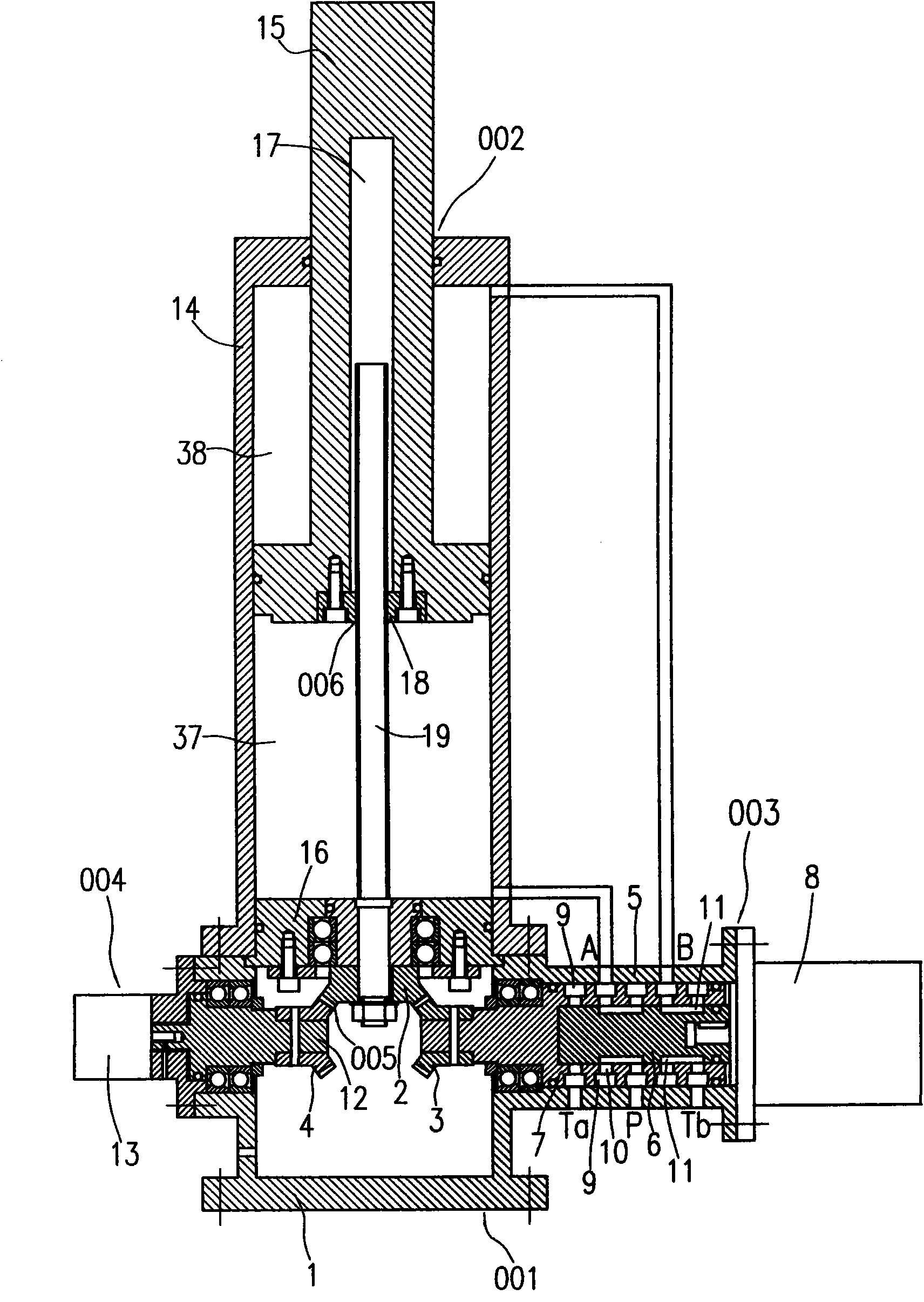
[0023] figure 1 It is a servo hydraulic cylinder including a servo hydraulic valve of the present invention. The servo hydraulic cylinder includes a servo hydraulic valve (001) and a hydraulic cylinder (002) combined with it. The servo hydraulic valve (001) includes a housing (1), a control valve (003), a sensor (004), and a gear pair (005). The gear pair (005) includes a driving gear (2), a driven gear A (3) and a driven gear B (4). The control valve (003) includes a valve housing (5), a valve core (6), a valve sleeve (7), and a stepping motor (8). One end of the valve sleeve (7) is fixedly connected with the driven gear A (3), and the valve core (6) is inserted into the inner hole of the valve sleeve (7). The valve housing (5) is a part of the housing (1), the stepping motor (8) is installed on the end surface of the valve housing (5), and its output shaft is inserted into the valve core (6). ) The inner hole at one end is connected with a key. The outer wall of the valve...


PUM


Abstract

Conventional pressure filters generally adopt hydraulic cylinder-driven opening/closing compression mechanisms, and have numerous disadvantages of unreliable multi-cylinder synchronous operation, bad control sensitivity and precision, and the like. The invention proposes an opening/closing compression mechanism driven by a hydraulic cylinder comprising a servo hydraulic valve or by a hydraulic motor in order to realize digital control over position, stroke, speed, pressure and other motion variables and adapt to the work characteristics and need of pressure filters better. The servo hydraulic valve has a hydraulic control valve controlled by a stepping motor, a position sensor and a pressure sensor, and is combined with the hydraulic cylinder or the hydraulic motor as a whole. The mechanism has the advantages of perfect control function, improved sensitivity, precision, work stability and reliability and use convenience. In addition, as a hydraulic system, a motion control system and an electric automatic control system are simplified and less in components, the servo hydraulic transmission mechanism is advanced, reasonable, economical and applicable.

Description

technical field [0001] The invention relates to the technical field of hydraulic transmission, in particular to a digitally controlled hydraulic control valve, an actuator and a filter press using the mechanism. Background technique [0002] Existing plate-frame and box-type filter presses generally use hydraulic cylinders to compress the filter plate, in which a pressure relay is used to control the pressing force, and a travel switch is used to control the return stroke. The control sensitivity or precision is relatively poor, and the control function is not perfect. In addition, multi-cylinder pressing lacks effective synchronous technical measures, and serious mechanical failures have occurred. U.S. Patent No. 6,099,725 uses two hydraulic cylinders arranged on both sides of the filter plate to complete the above three operations of pulling, closing, and pressing. A rack and pinion interlocking device is used to ensure the synchronous operation of the two hydraulic cylind...

Claims


Application Information

Patent Timeline
IPC IPC(8): F15B13/02B01D25/172
Inventor 宋家骏赵鸿才宋为
Owner 宋家骏
Why Eureka
Try Eureka