Bearing device of compressor for refrigerator

A bearing device, refrigerator technology, applied in the direction of bearings, bearing components, shafts and bearings, etc., can solve problems such as seizure, narrow bearing sliding surface and crankshaft surface, and reduced compression efficiency.

Inactive Publication Date: 2010-09-22
DAIDO METAL CO LTD
View PDF6 Cites 8 Cited by
  • Summary
  • Abstract
  • Description
  • Claims
  • Application Information

AI Technical Summary

Problems solved by technology

[0004] In this case, the sliding surface lubrication of the bearing of the compressor in the refrigerator can be achieved by feeding refrigerant or refrigerator oil into the gap between the bearing sliding surface and the surface of the crankshaft, however, since the compressor in the refrigerator starts The amount of oil fed is small, and the gap between the bearing sliding surface and the crankshaft surface is designed to be very narrow, which is easy to produce direct contact between the bearing sliding surface and the crankshaft surface
As disclosed in Patent Documents 1 and 2, bearings in which the porous metal sintered layer is sparsely exposed to the sliding surface can obtain satisfactory characteristics during normal operation, however, when the compressor starts, the porous metal sintered layer sparsely exposed to the sliding surface Direct contact is created between the metal sintered layer and the shaft surface, so bearing wear and surface seizure are prone to occur
In addition, by enlarging the gap between the bearing sliding surface and the crankshaft surface, the contact between the bearing sliding surface and the crankshaft surface at startup can be reduced, however, since the compression efficiency decreases due to the deflection of the crankshaft axis during normal operation, so , cannot be a practical solution

Method used


Image

  • Bearing device of compressor for refrigerator
  • Bearing device of compressor for refrigerator
  • Bearing device of compressor for refrigerator

Examples


Embodiment Construction

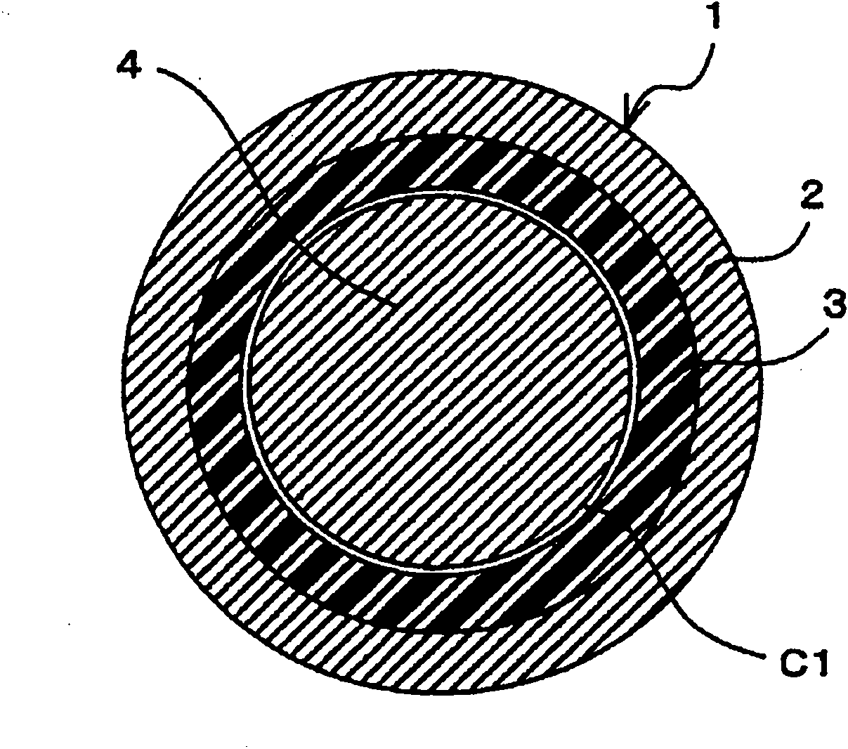
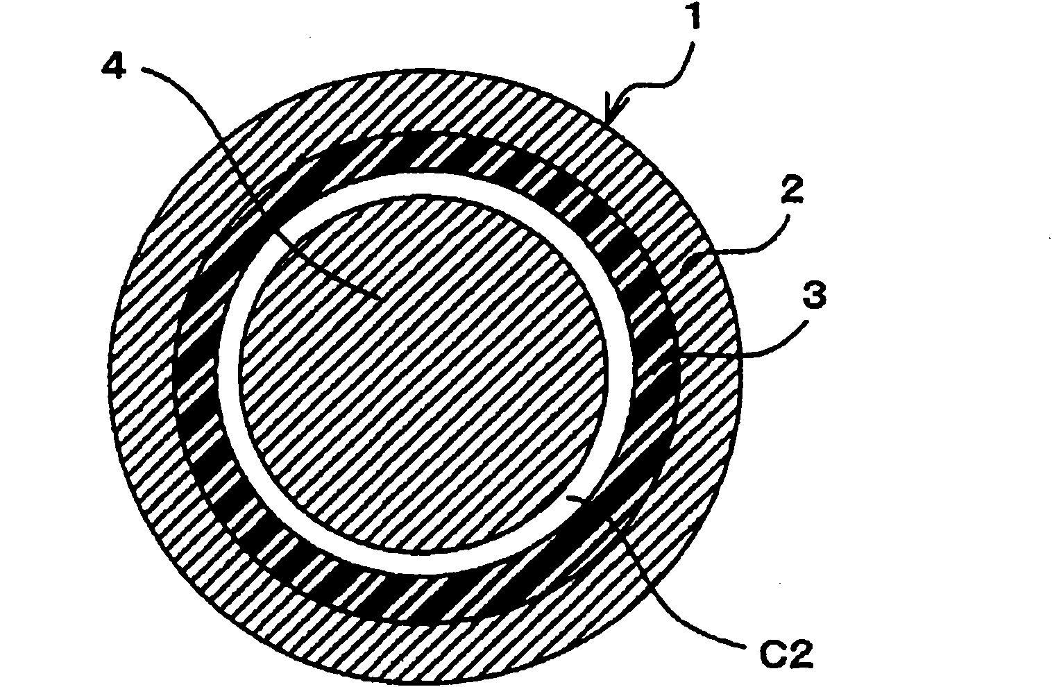
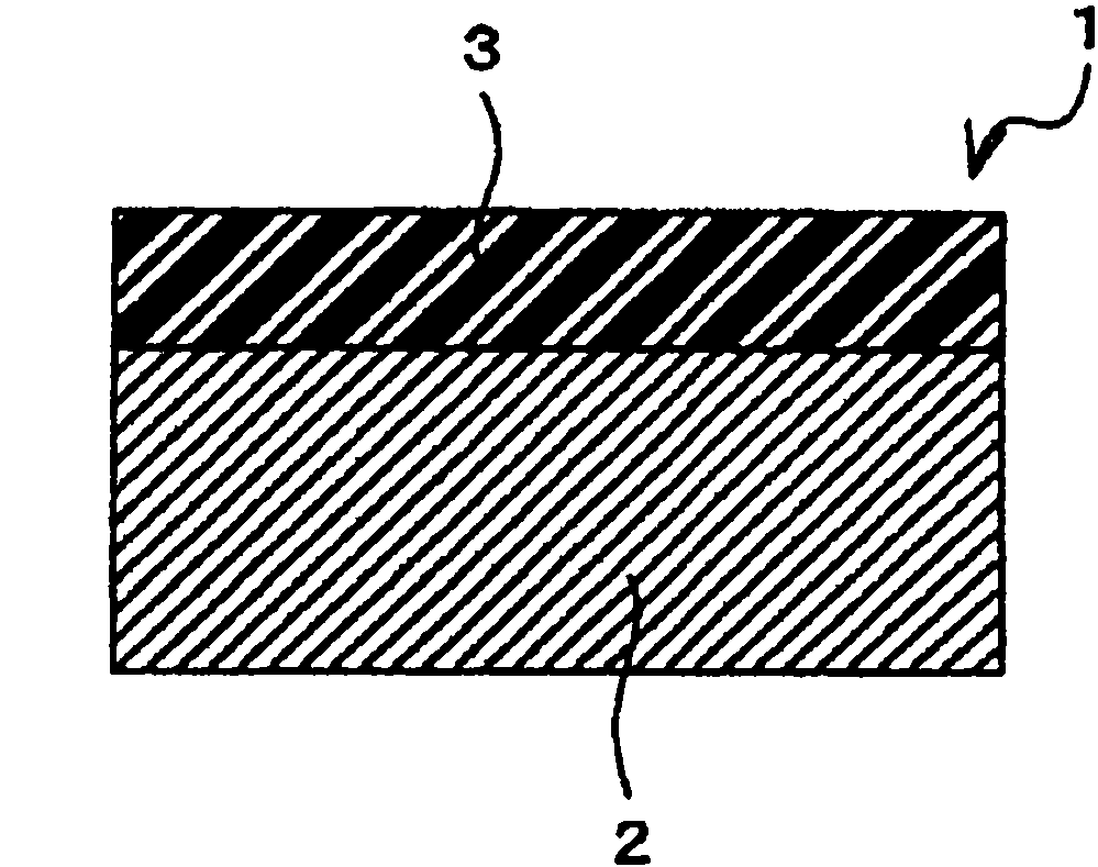
[0029] A description will be given below of an embodiment according to the present invention with reference to FIGS. 1 to 3 . Figure 1A is a cross-sectional view showing the relationship between crankshaft 4 and bearing 1 during normal operation of the compressor in refrigerant, Figure 1B is a sectional view showing the relationship between the crankshaft 4 and the bearing 1 at the start of the compressor in the refrigerant, figure 2 is a schematic cross-sectional view of a bearing 1 in which the resin sliding layer 3 is coated directly on the steel backing layer 2, and image 3 is a schematic cross-sectional view of a bearing 1 in which a porous metal sintered layer 5 is formed as an intermediate layer on a steel back layer 2 and a resin sliding layer 3 is coated on the porous metal sintered layer 5 . In this case, the above-mentioned drawings are schematic diagrams of the crankshaft 4 and the bearing 1 according to this embodiment, and each part is drawn exaggeratedly or ...


PUM


Abstract

The invention provides a bearing device of a compressor for a refrigerator which can widen a clearance between a sliding surface of a bearing and a surface of a crank shaft at a time of starting, while narrowing the clearance between the sliding surface of the bearing and the surface of the crank shaft at a time of a regular operation of the compressor for the refrigerator. A thickness of a resinsliding layer is set in such a manner that a bearing clearance at a starting time becomes relatively larger than a bearing clearance at a regular operating time within a range which is equal to or more than 2.5% and is equal to or less than 20%. Accordingly, since the bearing clearance becomes larger within the range which is equal to or more than 2.5% and is equal to or less than 20% at the starting time with respect to the regular operating time, while narrowing the bearing clearance for preventing a compression efficiency of the compressor for the refrigerator from being lowered due to a deflection of an axis of a crank shaft, at the regular operating time, it is possible to prevent a sliding surface of a bearing and a surface of the crank shaft from coming into direct contact with each other.

Description

technical field [0001] The present invention relates to a bearing device for a compressor in a refrigerator, which is constructed as a cylindrical bearing having a steel back layer and a resin sliding layer, the bearing rotatably supports a shaft through a gap. Background technique [0002] As the compressor in the refrigerating machine, there are various types of compressors such as screw type compressors, rotary type compressors, etc., however, no matter which type has a structure in which a bearing supports a crankshaft (rotary shaft) through clearance. In the bearing device of the compressor in the refrigerating machine, a cylindrical bearing or similar structure is used, which is constructed of a multilayer structure in which a porous metal sintered layer is formed on a steel backing layer, and a resin compound is impregnated into a sintered porous sintered metal in the interstices of the layer. In addition, the bearings of the compressors in refrigerators have been ma...

Claims


Application Information

Patent Timeline
Patent Type & Authority Applications(China)
IPC IPC(8): F16C33/20F16C33/10
CPCC10N2210/02F16C33/20C10M2201/085C10M2201/0653F04B27/1063C10M2201/0663F04B27/0865C10N2210/01C10M2213/0623C10M169/04F04C29/00C10N2240/30C10M2201/062C10M2201/0413C10N2250/14F04C2240/50C10M2201/084C10N2250/18C10N2240/02F05C2251/042C10N2010/02C10N2010/04C10N2040/02C10N2040/30C10N2050/023C10N2050/14F16C33/201F16C33/205F16C33/206F16C2202/50F16C2208/58F16C2240/60F16C2360/44
Inventor 岩田英树
Owner DAIDO METAL CO LTD
Why Eureka
Try Eureka