
Ultraviolet ray irradiator

An irradiation device, ultraviolet technology, applied in electrical components, semiconductor/solid-state device manufacturing, circuits, etc., can solve problems such as plate damage, reduced adhesive force of UV-curable dicing tape, blade damage, etc., to prevent damage, The effect of suppressing end material spatter

Active Publication Date: 2010-09-22
DISCO CORP
View PDF6 Cites 4 Cited by
  • Summary
  • Abstract
  • Description
  • Claims
  • Application Information

AI Technical Summary

Problems solved by technology

[0013] Depending on the type of plate-shaped object such as a semiconductor wafer, the end material will be smaller than the chip size, and there is a problem that the end material is easy to splash during cutting.
The spattered end material during cutting will damage the upper surface of the plate being processed and cause the plate to break. Not only that, if the spattered end material collides with the cutting blade, it will also cause damage to the blade
[0014] In particular, when UV-curable dicing tape is irradiated with ultraviolet light before cutting, the adhesive force of the UV-curable dicing tape is also reduced, so the end material is more likely to fly during cutting

Method used


Image

  • Ultraviolet ray irradiator
  • Ultraviolet ray irradiator
  • Ultraviolet ray irradiator

Examples


Embodiment Construction

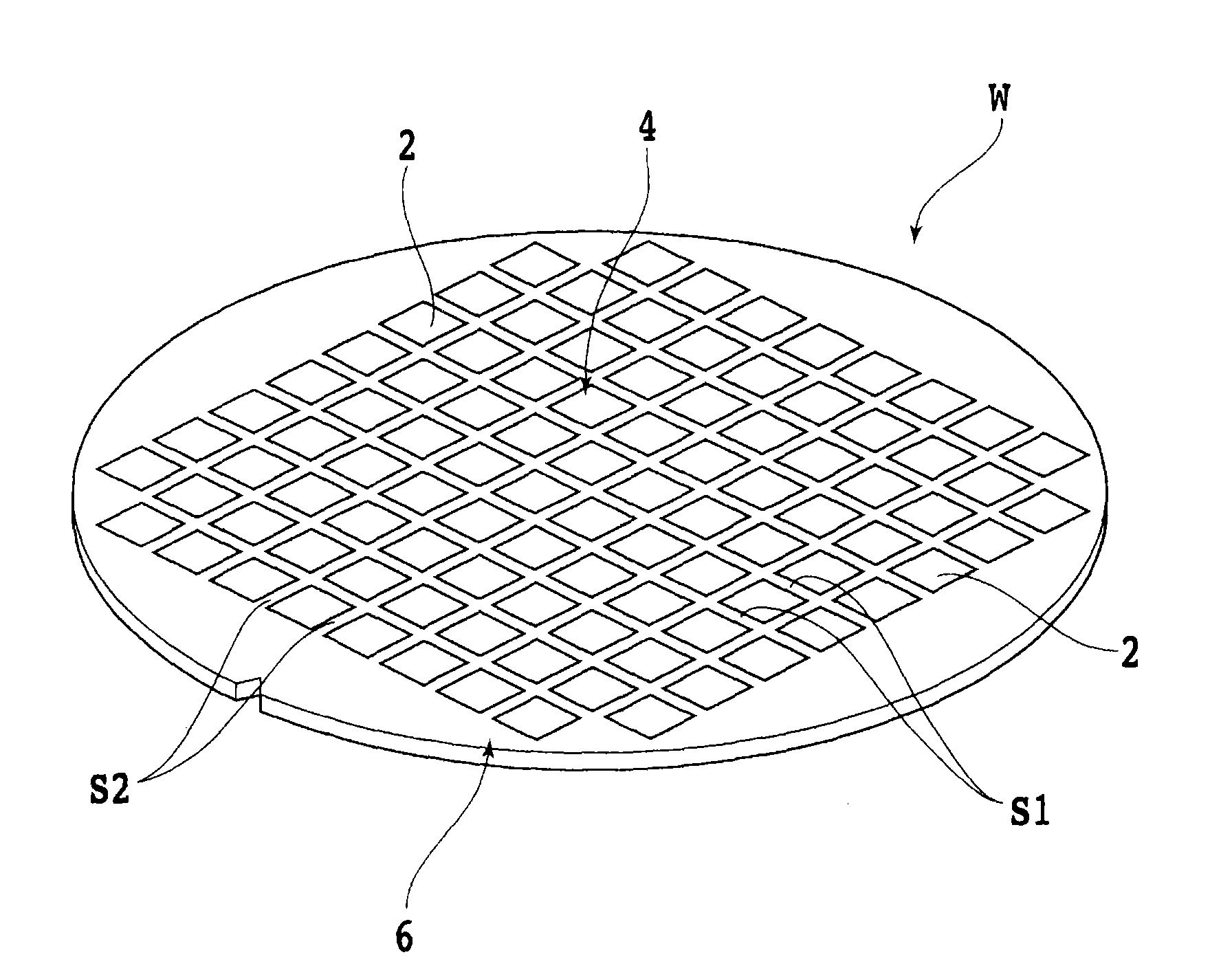
[0030] Hereinafter, embodiments of the present invention will be described in detail with reference to the drawings. like figure 1 As shown, a first straight line S1 and a second straight line S2 are orthogonally formed on the surface of a semiconductor wafer W, which is a kind of plate-shaped object to be cut, and the area divided by the first straight line S1 and the second straight line S2 is A plurality of chips (devices) 2 are formed therein. The semiconductor wafer W thus constituted includes: a chip region 4 in which the chip 2 is formed; and an outer peripheral end material region 6 surrounding the chip region 4 .

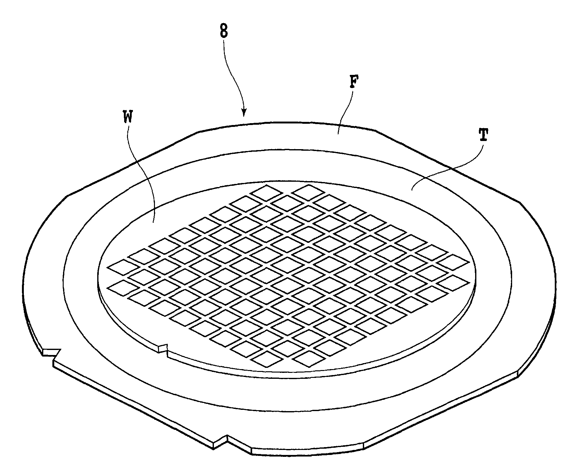
[0031] When cutting the semiconductor wafer W, such as figure 2 As shown, the back surface of the wafer W is attached to the adhesive surface of the ultraviolet curing dicing tape T, and the outer peripheral portion of the ultraviolet curing dicing tape T is attached to the ring frame F to form a wafer unit 8 and carry it. Thereby, the wafer W is in a s...


PUM


Abstract

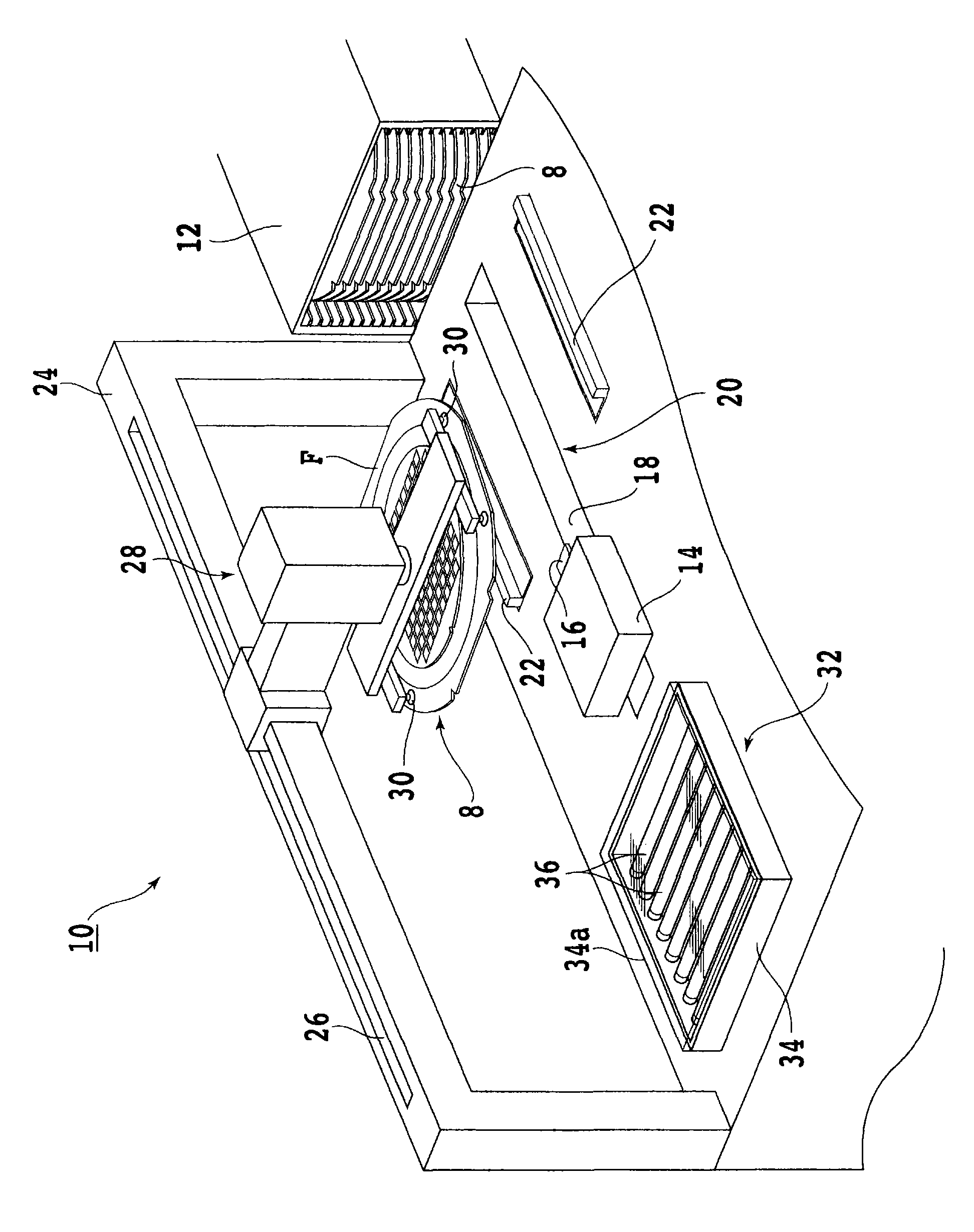
The present invention provides an ultraviolet ray irradiator which irradiates ultraviolet ray without conveying complication or damage to plate-shaped object and cutting blade. The ultraviolet ray irradiator irradiates ultraviolet ray to a plate-shaped object unit which is adhibited with the plate-shaped object on an ultraviolet solidification type carrier belt for solidifying the adhesive of the carrier belt. The peripheral part of the carrier belt is equipped to an annular frame. The ultraviolet ray irradiator comprises the following components: a box which can receive a plurality of plate-shaped object units; a supporting part which supports the plate-shaped object units; an ultraviolet ray irradiation unit which irradiates ultraviolet ray from a back surface of a plate-shaped object adhesion surface of the plate-shaped object unit to the carrier belt; a conveying unit which conveys the plate-shaped object units from the box to the supporting part and conveys the plate-shaped object unit from the supporting part after ultraviolet ray irradiation; a mask which is provided with an opening with an expected size for allowing the passing-through of the ultraviolet ray and shields the ultraviolet ray outside the opening; and a positioning unit which selectively positions the mask between the plate-shaped object unit and the ultraviolet ray irradiation unit, wherein when the mask is positioned between the plate-shaped object unit and the ultraviolet ray irradiation nit, the ultraviolet ray irradiation unit irradiates ultraviolet ray to the carrier belt through the opening.

Description

technical field [0001] The present invention relates to an ultraviolet irradiation device for irradiating ultraviolet rays to an ultraviolet curable carrier tape on which a plate-shaped object such as a wafer is attached and whose outer periphery is attached to a ring frame. Background technique [0002] As a processing device for cutting a plate-shaped object such as a semiconductor wafer, a ceramic plate, a glass plate, or a resin substrate, a cutting device called a cutter having a cutting blade is widely used. Such a cutting device is disclosed, for example, in JP-A-11-74228. [0003] The plate-shaped object cut by the cutting device is attached in advance to a dicing tape as an adhesive tape, and is mounted on a ring-shaped frame through the dicing tape. The cutting blade cuts into the middle of the thickness direction of the dicing tape while cutting the plate-shaped object, so that the plate-shaped object cut into a plurality of chips is not scattered and held on the...

Claims


Application Information

Patent Timeline
IPC IPC(8): H01L21/301
Inventor 久我卓也
Owner DISCO CORP
Learn More