
Dynamic voltage compensation device based on AC/AC converter

A dynamic voltage compensation and converter technology, applied in the direction of output power conversion devices, electrical components, etc., can solve the problems of high cost, complex topology, short life, etc., and achieve the effect of low cost, simple device and stable output voltage

Inactive Publication Date: 2012-08-22
SHANGHAI JIAOTONG UNIV +1
View PDF2 Cites 1 Cited by
  • Summary
  • Abstract
  • Description
  • Claims
  • Application Information

AI Technical Summary

Problems solved by technology

[0005] After searching the existing literature, it is found that the Chinese patent publication number is: CN201035433Y, and the name is: voltage regulator with bidirectional flow of energy. This technology uses DSP to control dual PWM converters to realize energy compensation for power grids. However, this technology uses capacitor charging. Discharging to achieve energy compensation requires the use of large-capacity capacitors, which are relatively expensive and have a relatively short life.
[0006] After searching, it was found that the Chinese patent publication number is: CN101521385A, and the name is: dynamic voltage compensator for three-phase power system. This technology uses two dynamic voltage compensators to realize three-phase voltage compensation, but this technology also requires energy storage Devices (such as batteries, capacitors or other energy storage elements) to achieve voltage compensation, making the topology more complex and costly

Method used


Image

  • Dynamic voltage compensation device based on AC/AC converter
  • Dynamic voltage compensation device based on AC/AC converter
  • Dynamic voltage compensation device based on AC/AC converter

Examples


Embodiment

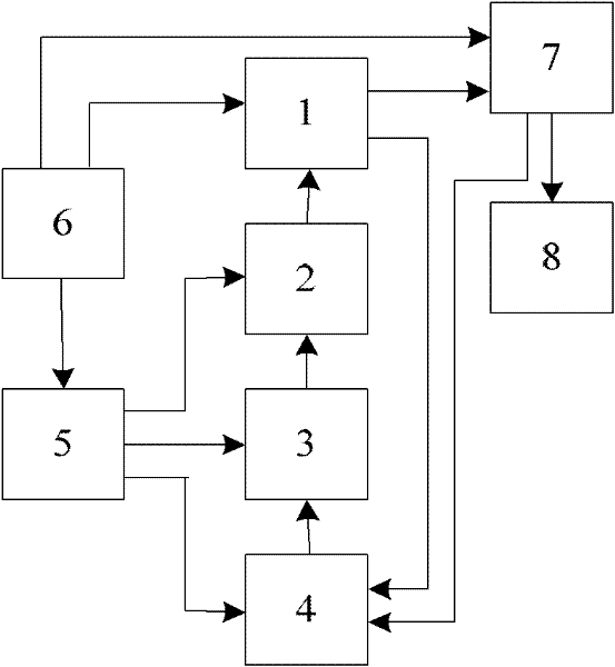
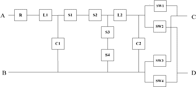
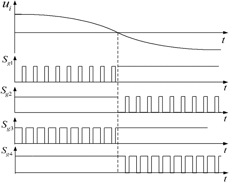
[0025] Such as figure 1 As shown, this embodiment includes: a power conversion main circuit module 1, a drive circuit module 2, a control signal generation module 3, a detection module 4, an auxiliary power supply module 5, an AC power supply 6 and a transformer module 7, wherein the AC power supply 6 is connected to The power conversion main circuit module 1, the auxiliary power supply module 5 and the transformer module 7 are connected to transmit AC power, the power conversion main circuit module 1 is connected to the drive circuit module 2 to transmit drive signals, and the drive circuit module 2 is connected to the control signal generation module 3 to transmit PWM control Signal, the control signal generating module 3 is connected to the power conversion main circuit module 1 to transmit compensation voltage polarity control signals, the detection module 4 is connected to the power conversion main circuit module 1 to transmit current and voltage signals, and the detection m...


PUM


Abstract

The invention discloses a dynamic voltage compensation device based on an AC / AC converter in the electric / electronic technical field, which comprises an AC power supply, a power conversion main circuit module, a drive circuit module, a control signal generation module, a transformer module, a detection module and an auxiliary power module. The AC power supply is connected with the power conversion main circuit module, the converter module and the auxiliary power module respectively; the power conversion main circuit module is connected with the drive circuit module and the transformer module respectively; the derive circuit module is connected with the control signal generation module; the detection module is respectively connected with the power conversion main circuit module and the control signal generation module; and the auxiliary power module is connected with the drive circuit module, the control signal generation module and the detection module respectively. The invention doesnot require large-capacity capacitor or inductor, has low cost and is easy to implement; moreover, the dynamic voltage compensation device has over-current protection function, can control the polarity and amplitude of the compensation voltage, and ensures stable output voltage when the input voltage rises or falls unexpectedly.

Description

Technical field [0001] The invention relates to a device in the field of power electronics technology, in particular to a dynamic voltage compensation device based on an AC / AC (alternating current / alternating current) converter. Background technique [0002] Voltage sag refers to a phenomenon in which the voltage amplitude drops to 10%-90% of the rated voltage amplitude, and the duration is half a cycle to a few seconds. Most of the voltage drops are caused by factors such as short-circuit faults in power distribution lines and induction motors starting. [0003] Sudden rise in voltage refers to the phenomenon of sudden rise in voltage amplitude. The main reason is that the instantaneous voltage rise generated by the line caused by the lightning strike or the operation of the circuit breaker, the line failure or other reasons cause the system parameters to change, causing the voltage to rise. [0004] When the power supply voltage rises or drops suddenly, the static stability of th...

Claims


Application Information

Patent Timeline
Patent Type & Authority Patents(China)
IPC IPC(8): H02M1/12
Inventor 金楠陈维威唐厚君蓝剑宇姚辰
Owner SHANGHAI JIAOTONG UNIV
Learn More