Low output loss LLC resonant converter

A resonant converter, low-output technology, applied in output power conversion devices, DC power input conversion to DC power output, instruments, etc., can solve the limitation of resonant converter efficiency improvement, large ripple current RMS, rectifier diodes The problem of large loss, etc., can solve the effect of large output capacitor ripple, smaller ripple, and reduced volume.

Inactive Publication Date: 2010-09-22
LIEBERT
View PDF6 Cites 41 Cited by
  • Summary
  • Abstract
  • Description
  • Claims
  • Application Information

AI Technical Summary

Problems solved by technology

Due to the voltage drop of the rectifier diode itself, when the output current is large, the loss on the rectifier diode is very large, which limits the efficiency of the resonant converter; moreover, the effective value of the ripple current of the output filter capacitor is relatively large, and the required filtering The capacitance is large, so it is not suitable for occasions where the output current is large

Method used


Image

  • Low output loss LLC resonant converter
  • Low output loss LLC resonant converter
  • Low output loss LLC resonant converter

Examples


specific Embodiment approach 1

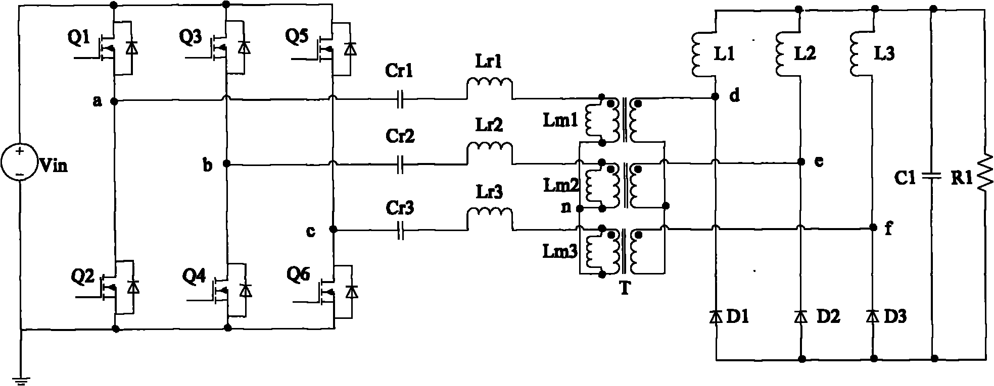
[0035] Such as figure 1 The three-leg LLC resonant converter shown is a typical three-leg LLC resonant converter, including an inverter, a resonant circuit, a three-phase transformer T, a rectifier circuit, and a filter circuit. The three-phase transformer T is connected in a Y~Y shape.

[0036] The inverter on the primary side of the three-phase transformer T consists of three bridge arms connected in parallel to invert the DC voltage into a square wave or ladder wave voltage. The lag angle between each bridge arm is 120°, that is, the second bridge arm composed of switching tubes Q3 and Q4 lags behind the first bridge arm composed of switching tubes Q1 and Q2 by 120°, and is composed of switching tubes Q5 and Q6 The third bridge arm lags behind the second bridge arm formed by switching tubes Q3 and Q4 by 120°, and the first bridge arm formed by switching tubes Q1 and Q2 lags behind the third bridge arm formed by switching tubes Q5 and Q6 120°. The driving signals of the ...

specific Embodiment approach 2

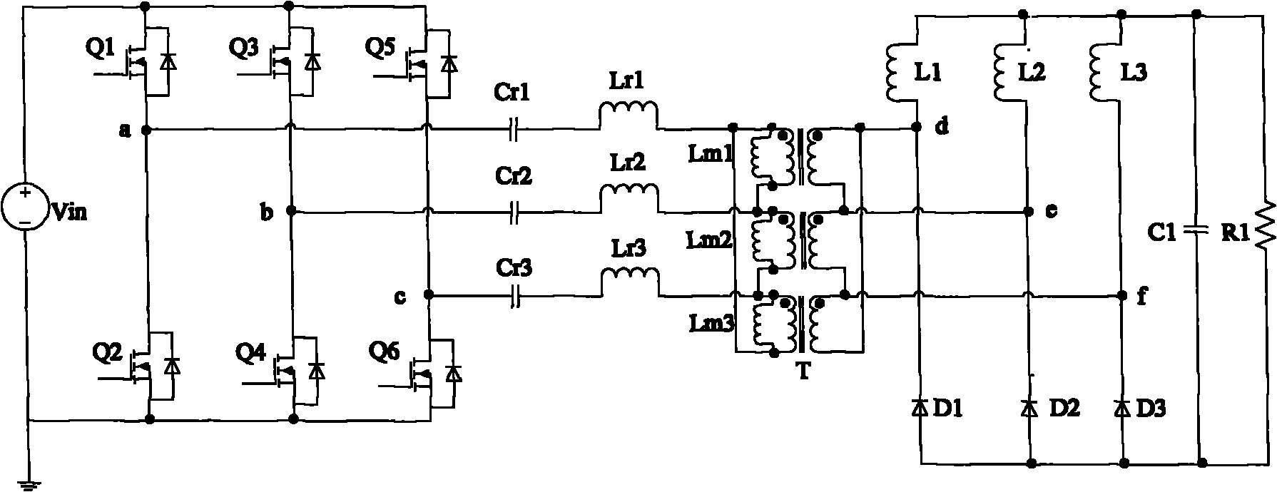
[0063] Such as figure 2 The three-leg LLC resonant converter shown is a modified three-leg LLC resonant converter, which also includes an inverter, a resonant circuit, a three-phase transformer T, a three-phase rectifier circuit, and a filter circuit. The difference from Embodiment 1 is that: the three-phase transformer T is connected in a Δ-Δ shape.

[0064] The second embodiment has basically the same beneficial effects as the first embodiment.

specific Embodiment approach 3

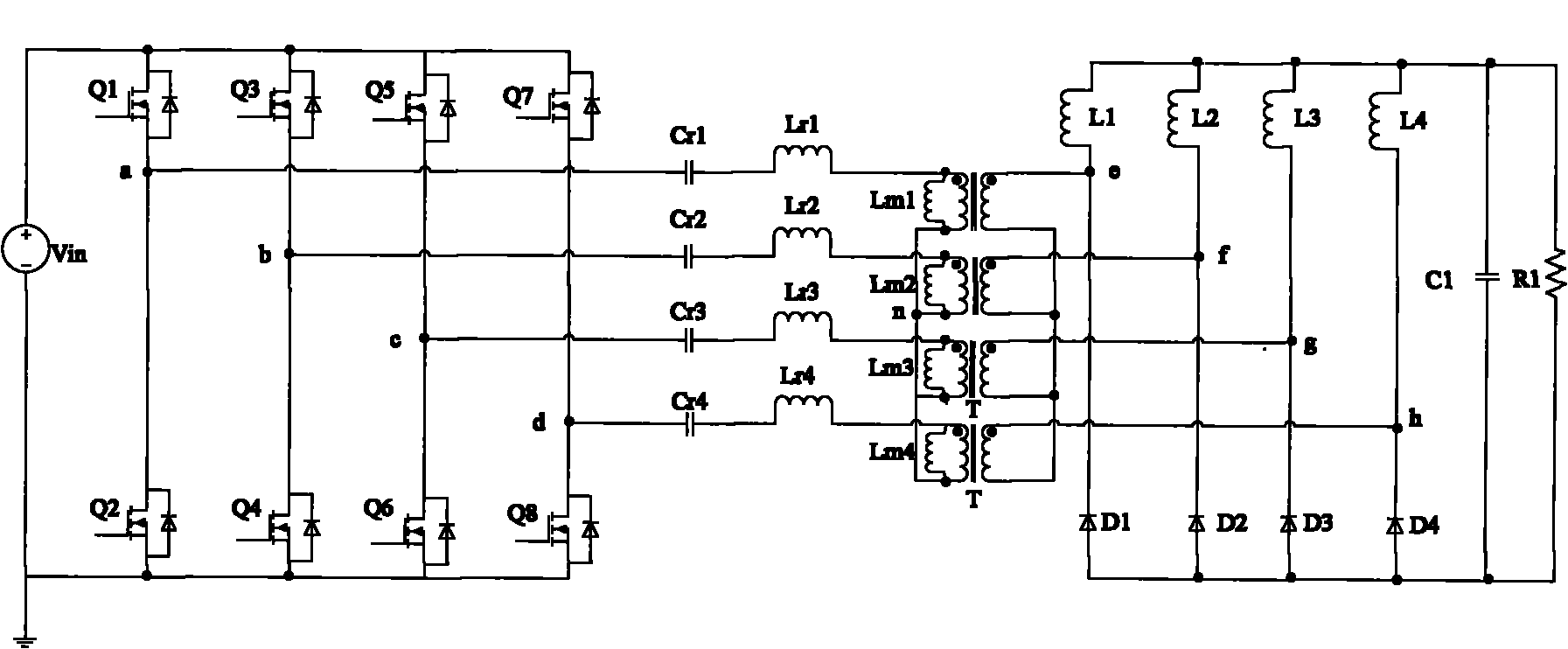
[0065]Such as image 3 The four-leg LLC resonant converter shown is a modified LLC resonant converter, including an inverter, a resonant circuit, a four-phase transformer, a four-phase rectifier circuit, and a filter circuit. One of the differences from Embodiment 1 is that the inverter on the primary side of the four-phase transformer T is composed of four bridge arms connected in parallel, and the lag angle between each bridge arm is changed from 120° of the three bridge arms to 90°. That is, the second bridge arm formed by switching tubes Q3 and Q4 lags behind the first bridge arm formed by switching tubes Q1 and Q2 by 90°, and the third bridge arm formed by switching tubes Q5 and Q6 lags behind the first bridge arm formed by switching tubes Q3 and Q6. The second bridge arm formed by Q4 is 90°, the fourth bridge arm formed by switch tubes Q7 and Q8 lags behind the third bridge arm formed by switch tubes Q5 and Q6 by 90°, and the fourth bridge arm formed by switch tubes Q1 a...


PUM


Abstract

The invention discloses a low output loss LLC resonant converter, comprising an inverter, a resonant circuit, a transformer and a filter circuit, wherein the inverter is formed by arranging at least three bridge arms in parallel, the resonant circuit is formed by at least three groups of resonant capacitances and resonant inductances which are connected in serial and at least three excitation inductances of the transformer with at least three phases, the transformer has at least three phases, the filter circuit is connected to the output end of a rectifying circuit, and the rectifying circuit is the rectifying circuit mixed by at least three phases, which is formed by at least three corresponding inductances and at least three corresponding rectifier tubes. The invention reduces the number of secondary-side output rectifier diodes of the transformer, obviously lowers the loss of an output rectifying circuit, and improves the efficiency of a resonant converter. The ripple frequency of the secondary-side output current of the transformer is at least three times of that of a half-bridge or full-bridge LLC resonant circuit which adopts the same switching tube frequency, and can adopt a filter element with smaller volume, so the volume of an output filter circuit is reduced.

Description

technical field [0001] The invention relates to resonant conversion, in particular to an LLC resonant converter with low output loss. Background technique [0002] Chinese patent CN1242539C announced a "LLC series resonant DC / DC converter", the DC / DC converter is a half-bridge LLC resonant converter, and its typical circuit is as follows Figure 7 shown. It contains a square wave generator with a half-bridge structure composed of two main switch tubes S1 and S2. The driving signal of the square wave generator is a complementary signal with a fixed 50% duty cycle, which is used to generate a series of square wave waveforms. The output voltage. The DC / DC converter also includes a resonant network connected to the square wave generator. The resonant network is composed of a series capacitor Cr, a series inductance Lr and a magnetizing inductance Lm, and is connected between the midpoint of the half bridge and the ground. The resonant capacitor Cr also acts as a DC blocking ca...

Claims


Application Information

Patent Timeline
Patent Type & Authority Applications(China)
IPC IPC(8): H02M3/337H02M1/14
CPCY02B70/1433Y02B70/10
Inventor 黄庆义胡永辉田瑞飞孟丽婵毕晓萌
Owner LIEBERT
Why Eureka
Try Eureka