Fast pyrolytic test device and application

A testing device and pyrolysis technology, applied in measurement devices, instruments, scientific instruments, etc., can solve the problems of temperature deviation, not, etc., and achieve the effects of simple operation, low equipment cost, and high cost performance.

Inactive Publication Date: 2010-09-29
SHANXI INST OF COAL CHEM CHINESE ACAD OF SCI
View PDF2 Cites 30 Cited by
  • Summary
  • Abstract
  • Description
  • Claims
  • Application Information

AI Technical Summary

Problems solved by technology

In addition, when using a fixed bed to investigate the gas, liquid, and solid yields at the pyrolysis temperature, since the pyrolysis process has already occurred during the slow temperature rise, there is a temperature deviation, so it is not really the gas at a certain pyrolysis temperature. , liquid, solid yield

Method used


Image

  • Fast pyrolytic test device and application
  • Fast pyrolytic test device and application
  • Fast pyrolytic test device and application

Examples


Embodiment 1

[0030] Fast pyrolysis of lignite:

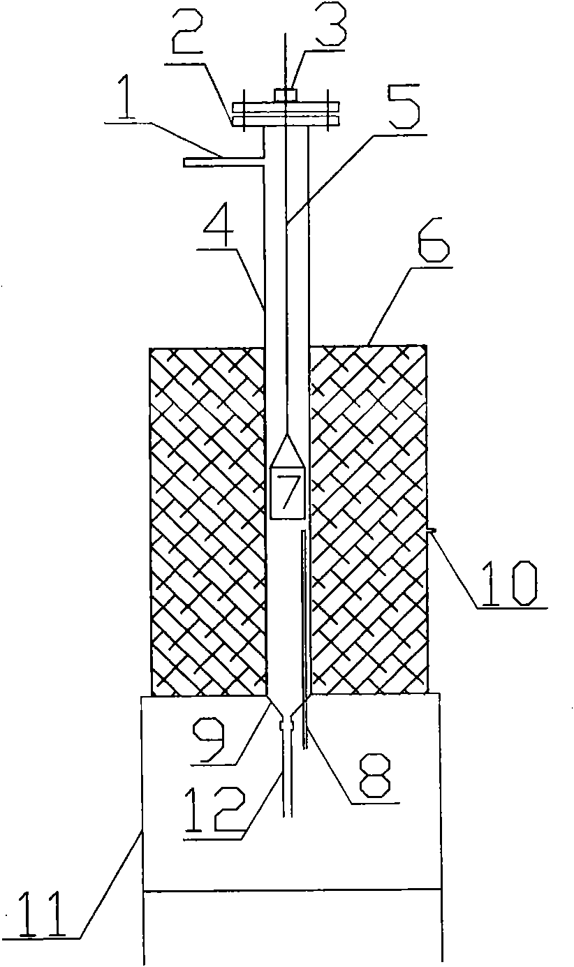
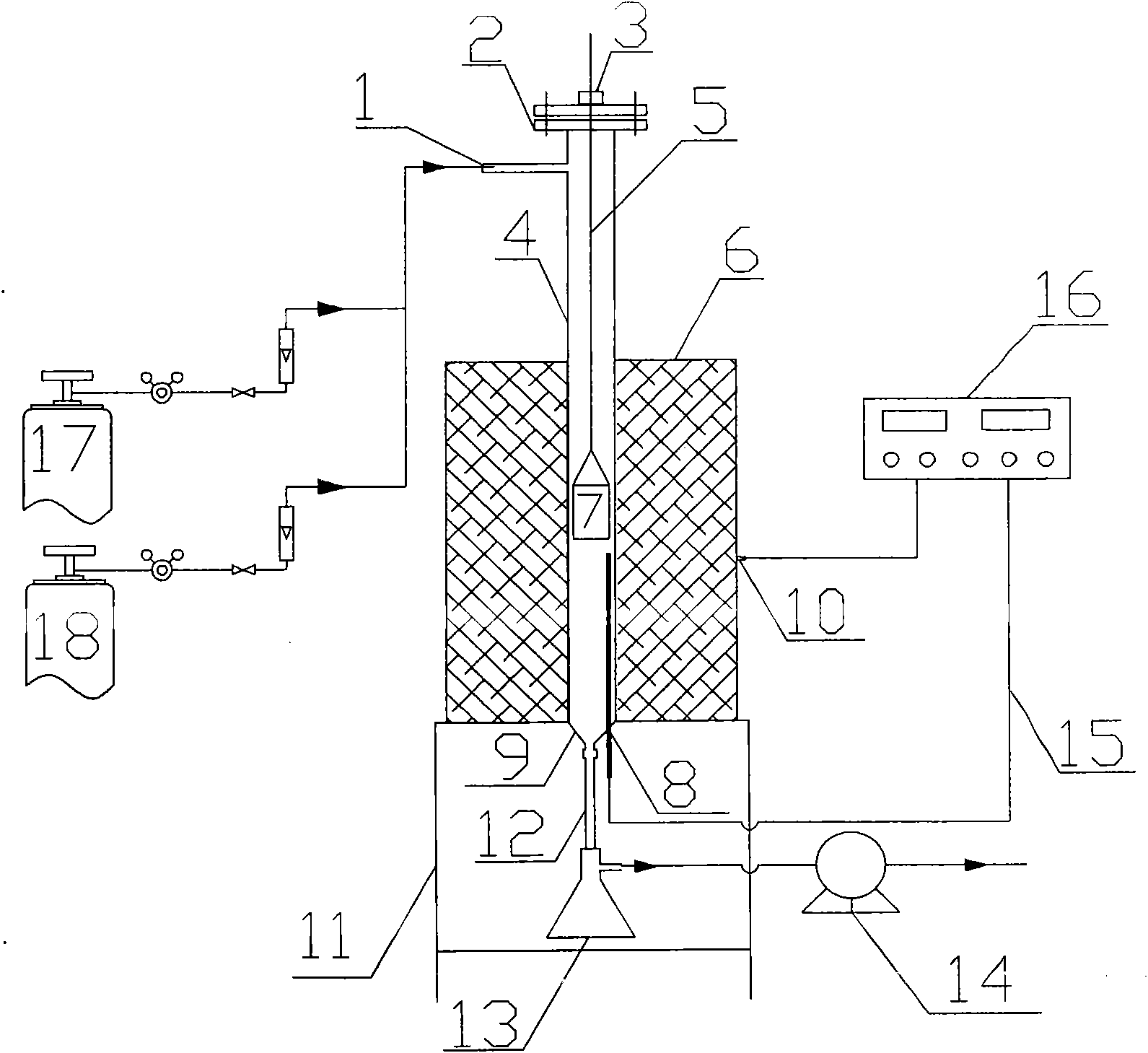
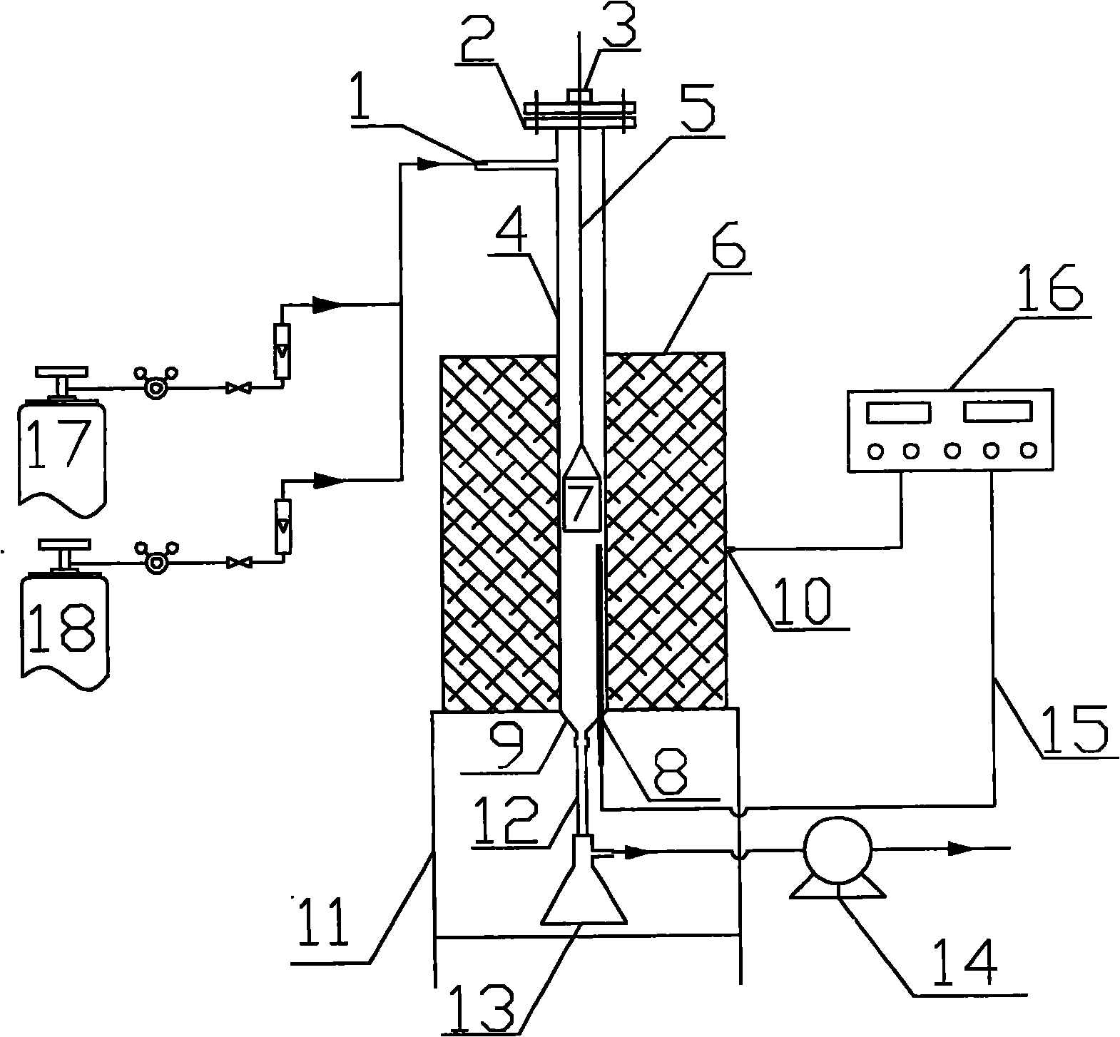
[0031] The upper part of the reaction tube 4 has an air inlet 1, the top of the reaction tube 4 has an adjustable seal 3, and there is a stainless steel rod 5 inside the reaction tube 4, the top of the stainless steel rod 5 is connected to the adjustable seal 3, and the lower end of the stainless steel rod 5 is connected to the sample. The hanging basket 7 is connected, the middle and lower part of the reaction tube 4 is located in the tubular electric heating furnace 6, the bottom of the reaction tube 4 has a temperature measuring port 8 and a conical oil and gas outlet 9, and the conical gas outlet 9 is connected to the oil and gas outlet 12, The tubular electric heating furnace 6 is located on the object rack 11 .

[0032] (1), the PTC-2 type temperature controller 16 produced by the Shanxi Coal Chemical Institute of the Chinese Academy of Sciences is connected with the thermocouple in the temperature measuring port 8 at the bottom of the...

Embodiment 2

[0042] Fast pyrolysis of corncob:

[0043] In this example, the raw material is corn cob with a particle size of less than 3mm, the amount of raw material is 2g, the temperature controller is AI-708 produced by Xiamen Yudian, the pyrolysis temperature is 900°C, the reaction atmosphere is methane, and the others are the same as in Example 1. . The pyrolysis data are shown in Table 1.

Embodiment 3

[0045] Fast pyrolysis of bagasse:

[0046] In this example, the raw material is bagasse with a particle size of less than 3 mm, the amount of raw material is 2 g, the temperature controller is SGM2843K produced by Sigma, the pyrolysis temperature is 800 ° C, and the reaction atmosphere is CO 2 , other with embodiment 1. The pyrolysis data are shown in Table 1.


PUM

PropertyMeasurementUnit
particle diameteraaaaaaaaaa

Abstract

The invention relates to a fast pyrolytic test device, which consists of a tubular electric heating furnace (6), an object carrying frame (11), a temperature test and control opening (8), a reaction tube (4), an air inlet opening (1) and an oil air outlet opening (9). The invention is characterized in that the air inlet opening (1) is arranged at the upper part of the reaction tube (4), the top of the reaction tube (4) is provided with an adjustable sealing element (3), a stainless steel rod (5) is arranged in the reaction tube (4), the top end of the stainless steel rod (5) is connected with the adjustable sealing element (3), the lower end of the stainless steel rod (5) is connected with a sample hanging basket (7), the middle lower part of the reaction tube (4) is positioned inside the tubular electric heating furnace (6), the bottom of the reaction tube (4) is provided with the temperature test and control opening (8) and the conical oil air outlet opening (9), the conical oil air outlet opening (9) is connected with an oil air outlet tube (12), and the tubular electric heating furnace (6) is positioned on the object carrying frame (11). The invention has the advantages of high performance price ratio, simple and convenient operation, simple structure and low equipment cost, can realize slow temperature rise and fast pyrolysis under the condition of simulated work conditions, can realize fast cooling, and can accurately measure the tar amount generated by the pyrolysis.

Description

technical field [0001] The invention belongs to a test device and application, in particular to a test device and application for preparing semi-coke and obtaining solid, liquid and gas yields under fast pyrolysis conditions for carbonaceous substances such as coal and biomass . technical background [0002] At present, coal or biomass gasification generally undergoes rapid pyrolysis at high temperature into semi-coke in gasifiers (fluidized bed and entrained flow bed), and then gasifies. Therefore, when examining the gasification kinetics of coal or biomass, the semi-coke is usually obtained first, and then the gasification kinetics of the semi-coke is investigated. However, at present, when preparing semi-coke, the raw materials are generally put into a fixed bed first, and then the temperature of the fixed bed is slowly raised to the pyrolysis temperature, and then stayed for a period of time, and then slowly cooled to obtain semi-coke. In addition, when using a fixed b...

Claims


Application Information

Patent Timeline
Patent Type & Authority Applications(China)
IPC IPC(8): G01N25/12G01N5/00
Inventor 张永奇任海君房倚天黄戒介赵建涛涂峰夏立森李风海
Owner SHANXI INST OF COAL CHEM CHINESE ACAD OF SCI
Why Eureka
Try Eureka