Printed circuit board

A technology of printed circuit board and power supply, which is applied in the direction of printed circuit, printed circuit, printed circuit manufacturing, etc., can solve the problems of increasing cost, achieve the effect of reducing input impedance, reducing cost and increasing capacitance

Inactive Publication Date: 2010-09-29
HONG FU JIN PRECISION IND (SHENZHEN) CO LTD +1
View PDF2 Cites 6 Cited by
  • Summary
  • Abstract
  • Description
  • Claims
  • Application Information

AI Technical Summary

Problems solved by technology

Although a single capacitor is relatively cheap, if a large number of decoupling capacitors are used on a mass-produced printed circuit board, it will greatly increase the cost

Method used


Image

  • Printed circuit board
  • Printed circuit board
  • Printed circuit board

Examples


Embodiment Construction

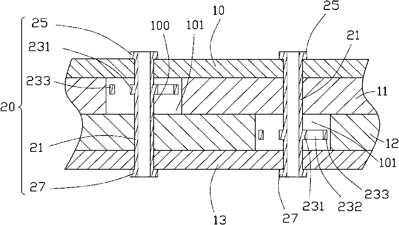
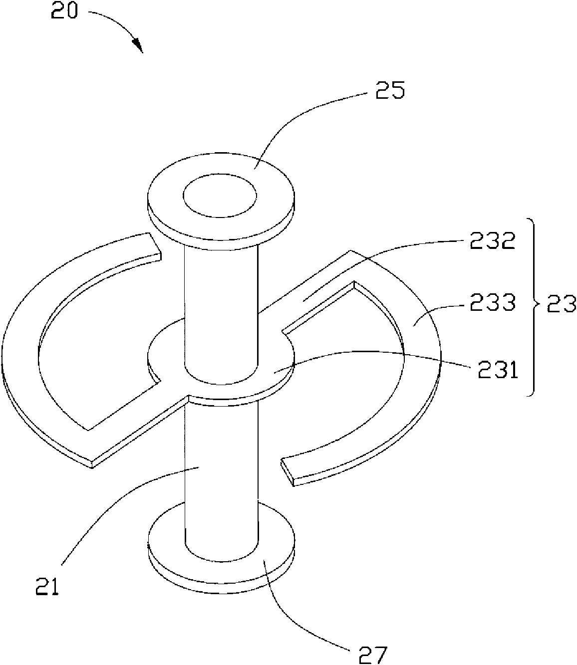
[0011] Please refer to figure 1 and figure 2 A preferred embodiment of the printed circuit board of the present invention includes a first signal layer 10 , a power layer 11 , a ground layer 12 and a second signal layer 13 sequentially placed from top to bottom. A plurality of grounding vias and a plurality of power supply vias 100 are longitudinally disposed on the printed circuit board. The part of the ground via located on the power layer 11 and the part of the power via located on the ground layer 12 are enlarged to form an isolation space 101 . Each ground via hole and power via hole 100 forms a conductor 20 . Each conductor 20 includes a cylindrical main body 21 located in the via hole 100 , an extension 23 disposed around the main body 21 , and pads 25 and 27 disposed at two ends of the main body 21 . Wherein, the pad 25 is located on the first signal layer 10 , the pad 27 is located on the second signal layer 13 , and the extension 23 is located in the isolation sp...


PUM


Abstract

The invention discloses a printed circuit board, which comprises a power supply layer, a grounding layer, and a plurality of grounding through holes and power supply through holes running through the power supply layer and the grounding layer, wherein a part of the grounding through holes positioned on the power supply layer and a part of the power supply through holes positioned on the grounding layer form an isolated space; a conductive body is arranged in each grounding through hole and each power supply through hole; and each conductive body forms an extension piece in the corresponding isolated space to enlarge the opposite area between the power supply layer and the grounding layer. The printed circuit board improves the electric capacity and reduces the input impedance by enlarging the opposite area between the power supply layer and the grounding layer.

Description

technical field [0001] The invention relates to a printed circuit board, in particular to a printed circuit board with stable voltage output. Background technique [0002] There are various power supplies on the printed circuit board, such as 5V, 1.5V, 3.3V DC power supplies and various AC power supplies. In order to reduce the interference of AC power noise to the signal, a large number of decoupling capacitors are usually connected between the power via and the ground via to ensure that the printed circuit board has a low input impedance to stabilize the AC power. Traditional power vias and ground vias are separated from the ground layer and the power layer respectively by setting isolation areas. Although individual capacitors are relatively inexpensive, using a large number of decoupling capacitors on a mass-produced printed circuit board can add significantly to cost. Contents of the invention [0003] In view of the above, it is necessary to provide a printed circu...

Claims


Application Information

Patent Timeline
Patent Type & Authority Applications(China)
IPC IPC(8): H05K1/02H05K1/11
CPCH05K3/429H05K1/116H05K2201/09309H05K2201/09781H05K1/0251H05K2201/09454H05K2201/09718
Inventor 白育彰刘建宏谢博全
Owner HONG FU JIN PRECISION IND (SHENZHEN) CO LTD
Why Eureka
Try Eureka