

Fluidized-bed incinerator and method of fluidized-bed incineration of sludge with the same
A technology of incinerators and fluidized furnaces, which is applied in the direction of combustion methods, fluidized bed combustion equipment, fuels burned in a molten state, etc., to achieve the effect of reducing consumption
- Summary
- Abstract
- Description
- Claims
- Application Information
AI Technical Summary
Problems solved by technology
Method used
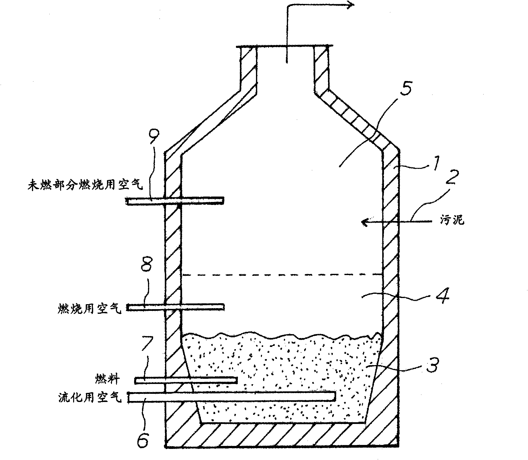
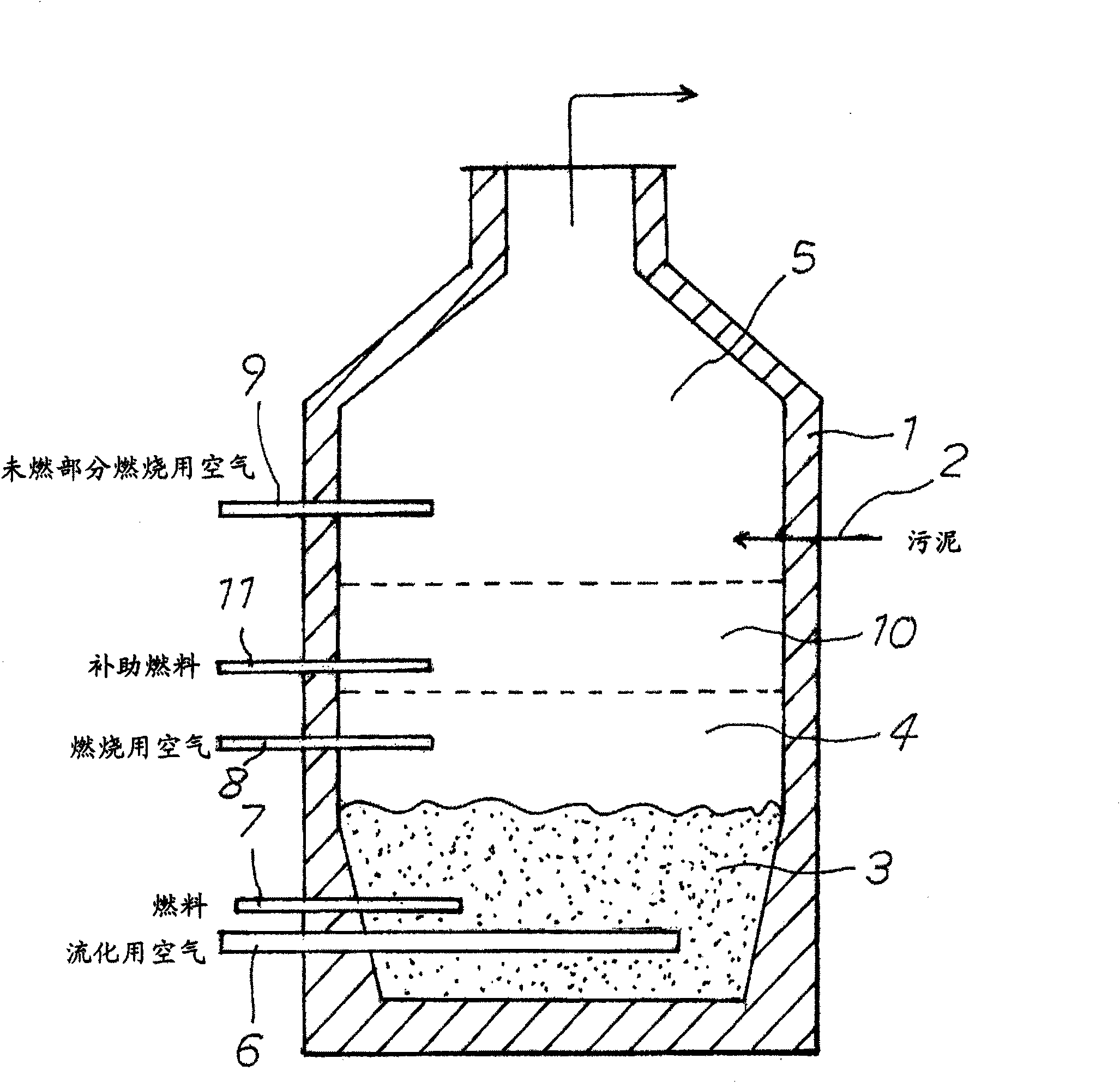
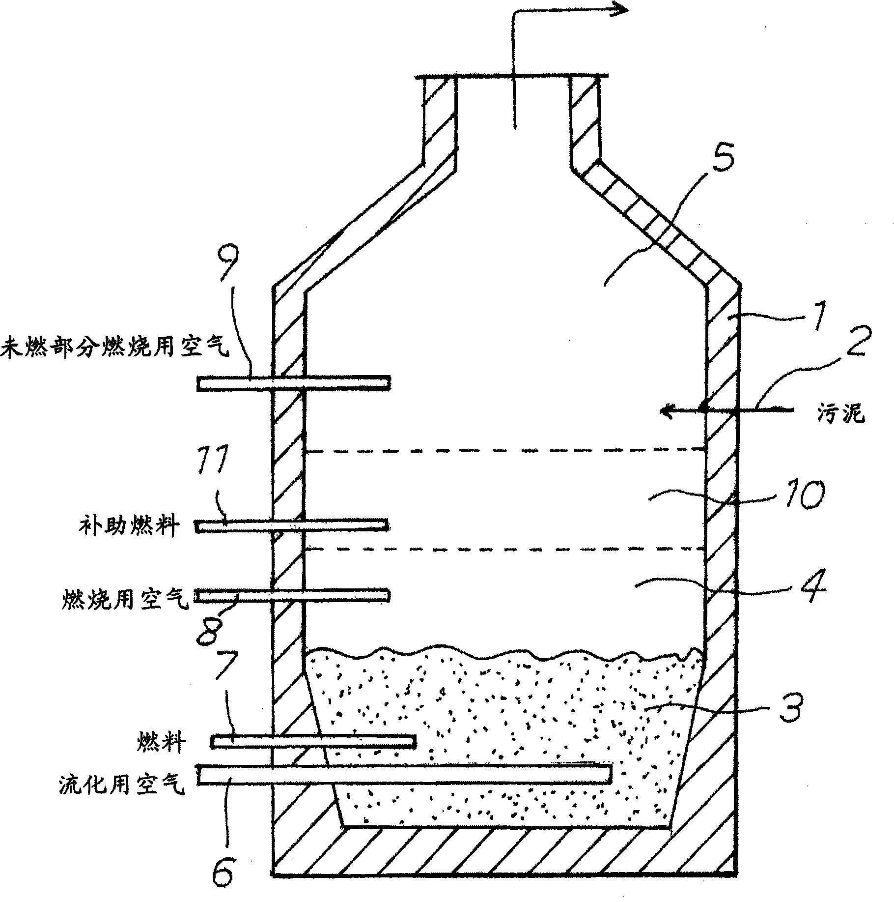
Image

Examples
Embodiment 1
[0046] The sludge incineration experiment was performed while changing the conditions using a fluidized furnace for the experiment. The input amount of sludge is all 80kg / h, and A heavy oil is used as auxiliary fuel. Experiments are as follows 4 kinds: conventional fluidized incineration, high temperature incineration with increased incineration temperature, and the present invention figure 1 The method shown, the present invention figure 2 method shown. It should be noted that, with respect to the present invention figure 2 In the method shown, propane gas was used in an amount corresponding to 300 ppm of the exhaust gas amount as the auxiliary fuel supplied from the auxiliary fuel supply pipe. For various incineration methods, the amount of supplementary fuel used (expressed as the calorific value of supplementary fuel per 1 kg of sludge), the temperature of the free air space (free board), the temperature of the furnace outlet, and the amount of nitrogen contained in t...
Embodiment 2
[0051] In the same manner as in Example 1, using a fluidized furnace for an experiment, the conditions were changed so that the amount of auxiliary fuel used could be further reduced, and a sludge incineration experiment was performed. The input amount of sludge was all 80 kg / h, and A heavy oil was used as auxiliary fuel. For various incineration methods, the amount of auxiliary fuel used (expressed as the calorific value of auxiliary fuel per 1 kg of sludge), the temperature of the free air space, the temperature of the furnace outlet, and the amount of nitrogen contained in the furnace were measured. 2 The concentration of exhaust gas components of O, the total excess air factor, the 1st excess air factor, and the 2nd + 3rd excess air factor are listed in Table 2.
[0052] [Table 2]
[0053]
[0054] Table 2 shows that the figure 1 In the method, while keeping the total excess air ratio constant, the primary excess air ratio is sequentially reduced from 1.2 to 0.9 data....
PUM
 Abstract
Description
Claims
Application Information