Nozzle heating type drying equipment

A drying equipment and heating technology, applied in printing, lamination auxiliary operations, printing machines, etc., can solve the problems of complex and large equipment and limit the scope of application, so as to ensure the drying speed, improve the drying performance, prevent Surface dry effect

Inactive Publication Date: 2010-10-06
VERBOCA ENERGY SAVING TECH CO LTD
View PDF9 Cites 16 Cited by
  • Summary
  • Abstract
  • Description
  • Claims
  • Application Information

AI Technical Summary

Problems solved by technology

This utility model undoubtedly has obvious progress in improving drying performance, energy saving and safety, but the equipm

Method used


Image

  • Nozzle heating type drying equipment
  • Nozzle heating type drying equipment
  • Nozzle heating type drying equipment

Examples


specific Embodiment 1

[0050] The drying equipment described in this embodiment is suitable for a coating machine.

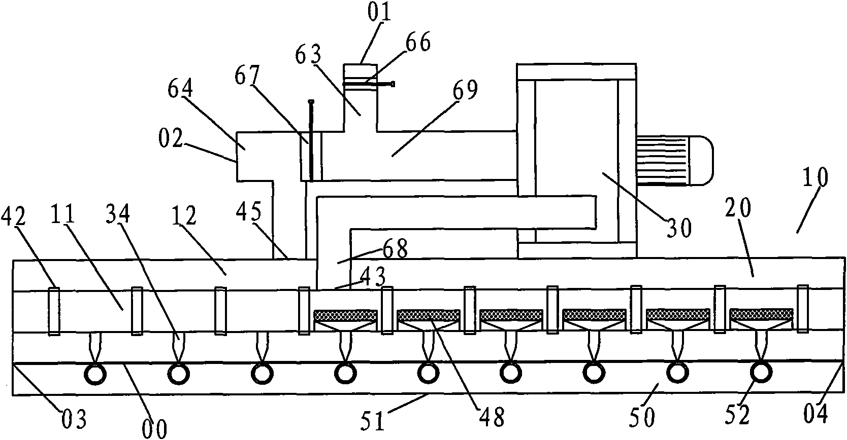
[0051] refer to figure 1 , the present embodiment includes an oven 10, a fan 30 and a heater 48, and the air outlet of the fan communicates with the inner cavity of the oven; the oven 10 includes an oven cover 20 and a base 50, between which there is a The transmission channel of the product; the air inlet cavity 11 is arranged in the oven cover, and several nozzles 34 are arranged above the transmission channel in the oven cover 20; the nozzles 34 communicate with the air intake cavity 11 or are arranged in the air intake cavity 11; The heater 48 is installed in the nozzle (34); the air outlet of the fan 30 communicates with the air inlet 43 of the air inlet cavity 11 through the air inlet passage 68.

[0052] Wherein: the blower fan 30 is installed on the oven 10, and the air outlet of the blower fan communicates with the oven inner cavity, or the blower fan 30 is installed beside...

specific Embodiment 2

[0064] The drying equipment described in this embodiment is suitable for a coating machine. It aims at improving the shortcoming of specific embodiment 1 that the energy-saving effect is not significant.

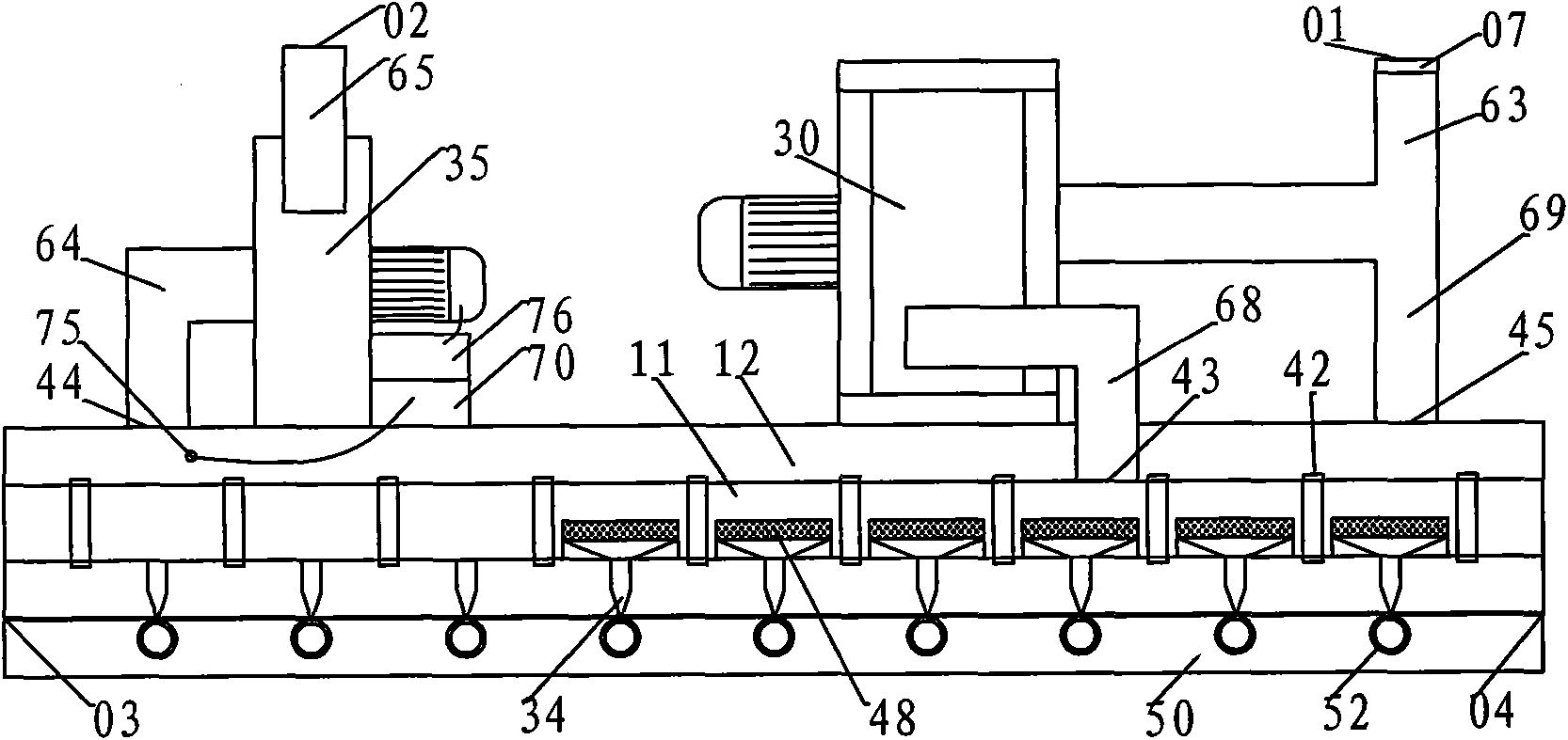
[0065] refer to figure 2 , The drying equipment described in this embodiment is composed of an oven 10, a fan 30, an exhaust fan 35, a control drive device 70, a connecting air duct, and an exhaust system.

[0066] The oven 10 includes an oven cover 20, a base 50, and is provided with a printed product inlet 03 and a printed product outlet 04;

[0067] The oven cover 20 includes an air inlet chamber 11 , an air exhaust chamber 12 , ten nozzles 34 , and ten heaters 48 .

[0068] The air inlet cavity 11 is provided with an air inlet 43 , which communicates with the air outlet of the fan 30 through the air inlet channel 68 .

[0069] The heater 48 is installed in the nozzle 34 , and the nozzle 34 is installed in the air inlet cavity 11 .

[0070] The air exhaust cavity 12 ...


PUM


Abstract

The invention relates to a piece of nozzle heating type drying equipment, which comprises a drying oven (10), a fan (30), and heaters (48). An air outlet of the fan is communicated with an inner cavity of the drying oven; and the drying oven (10) comprises a drying oven cover (20) and a base (50), and a delivery channel for delivering prints is arranged between the drying oven cover (20) and the base (50). The nozzle heating type drying equipment is characterized in that: 1) an air inlet cavity (11) is formed inside the drying oven cover, a plurality of nozzles (34) are arranged inside the drying oven cover (20) and on the upper part of the delivery channel; the nozzles (34) are communicated with the air inlet cavity (11) or arranged inside the air inlet cavity (11); the heaters (48) are arranged inside the nozzles (34); and the air outlet of the fan (30) is communicated with an air inlet (43) of the air inlet cavity (11) through an air inlet channel (68). The nozzle heating type drying equipment is widely applied to coating machines, compound machines, printing machines, roller coating lines, gluing machines, and similar processing equipment, and also can be used for drying continuously delivered objects.

Description

technical field [0001] The invention relates to a nozzle-heating drying equipment, which is suitable for drying continuously traveling thin strip-shaped objects (hereinafter referred to as printed products), and is widely used in coating machines, compound machines, printing machines, roller coating lines, and gluing machines. And similar processing equipment can also be used to dry continuously conveyed items. It belongs to the technical field of drying equipment such as printing and coating. Background technique [0002] At present, the processing equipment for thin strip objects generally has the following characteristics: the printed product is a thin strip object that travels continuously, such as plastic film, thin metal plate, etc. Continuous processing in the process. The surface of the processed product or product substrate is first covered with one or more layers of substances, such as ink, paint, glue, etc., using the transfer device of the equipment, and these ...

Claims


Application Information

Patent Timeline
IPC IPC(8): B05D3/02B41F23/04B32B38/16
Inventor 简甦
Owner VERBOCA ENERGY SAVING TECH CO LTD
Why Eureka
Try Eureka