Convenient rapid supporting loading and unloading mechanism and supporting loading and unloading method

A steel support and flange technology, applied in the field of loading, unloading mechanism and steel support, can solve the problems of support failure, inability to dismantle, and many construction processes, and achieve the effects of improving construction efficiency, shortening construction time, and safe and easy operation.

Inactive Publication Date: 2010-10-06
顾宝洪 +1
View PDF4 Cites 13 Cited by
  • Summary
  • Abstract
  • Description
  • Claims
  • Application Information

AI Technical Summary

Problems solved by technology

However, in practical applications, this kind of steel support also exposes its insurmountable shortcomings: during the installation process of the support, the prestressing process requires the cooperation of a crane and two loading jacks, and there is no data collection record for the pressurization value. The value depends on the experience and responsibility control of the operator, and there are many construction techniques and a long time; in addition, during the demolition process, due to the long-term stress and deformation of the steel wedge, it is difficult to dismantle, or even impossible to dismantle. Due to the excavation and deformation of the foundation pit, the axial force attenuation of some supports will occur, and even the support will fail; although the measure of adding axial force twice can be adopted on the construction site, there are many difficulties in the construction of the second adding axial force on site. This problem cannot be solved essentially; moreover, the installation and removal of the steel support requires the cooperation of the crane and the operator, and the process is complicated and unsafe, so it has the disadvantage of consuming labor and time

Method used


Image

  • Convenient rapid supporting loading and unloading mechanism and supporting loading and unloading method
  • Convenient rapid supporting loading and unloading mechanism and supporting loading and unloading method
  • Convenient rapid supporting loading and unloading mechanism and supporting loading and unloading method

Examples


Embodiment Construction

[0038] Now in conjunction with accompanying drawing and embodiment the invention is described in further detail.

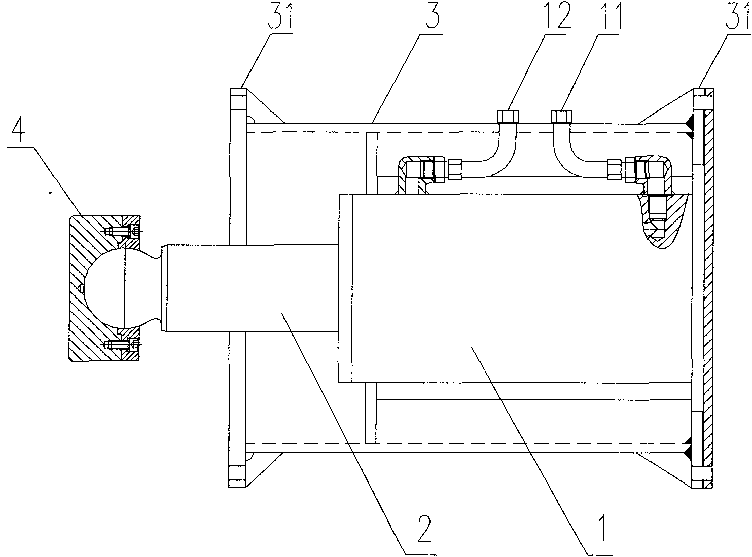
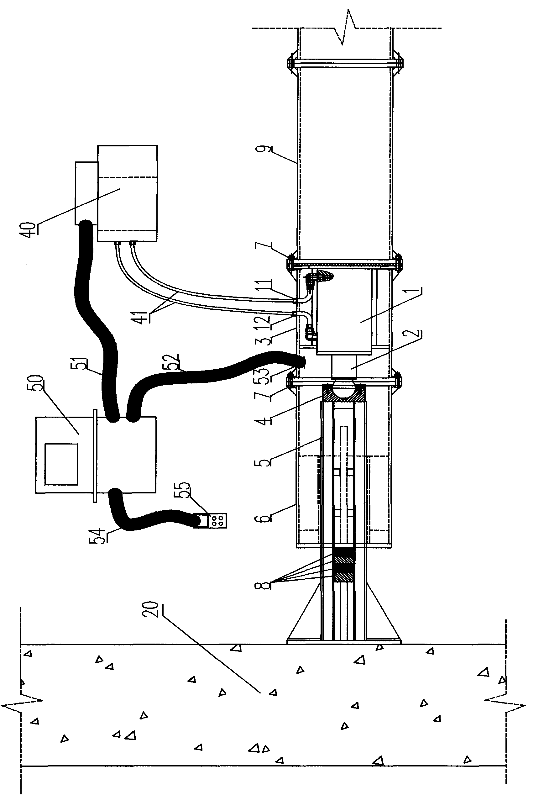
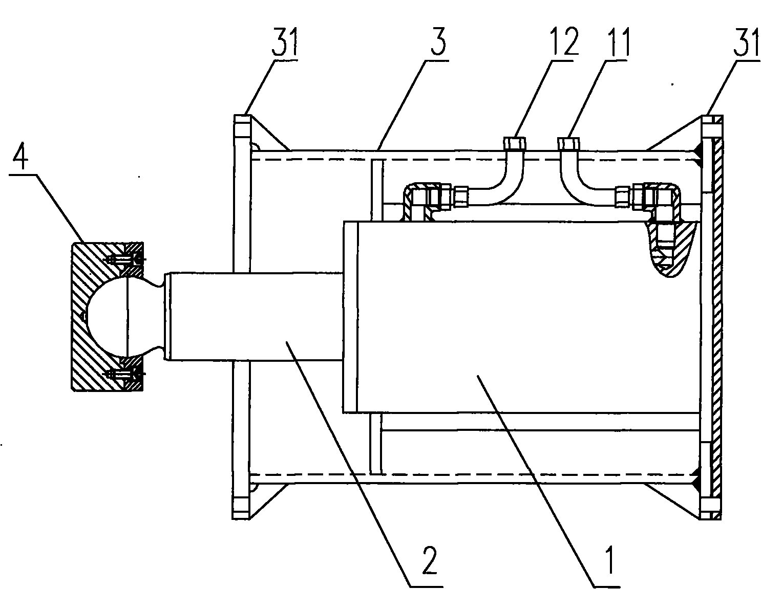
[0039] see figure 1 with figure 2 . The traditional steel support consists of a steel support end structure 6 , a support active joint 5 and a standard section support 9 .

[0040] The supporting loading and unloading mechanism of the present invention includes: a hydraulic cylinder 1, a cylinder piston rod 2, a steel support sleeve 3, the hydraulic cylinder 1 is provided with an oil inlet pipe port 11 and an oil return pipe port 12, and the steel support sleeve 3 is provided with a front end steel method The flange 31 and the rear-end steel flange 32, the front-end steel flange 31 and the rear-end steel flange 32 are respectively provided with connecting holes 311, 321 and the like.

[0041]The hydraulic cylinder 1 with built-in travel sensor and pressure sensor (not shown in the figure) is installed and fixed in the steel support sleeve 3, and the oil inlet ...


PUM


Abstract

The invention discloses a convenient rapid supporting loading and unloading mechanism and a supporting loading and unloading method. The supporting loading and unloading mechanism comprises a hydraulic oil cylinder, an oil cylinder piston rod and a steel supporting sleeve, wherein the hydraulic oil cylinder is provided with an oil inlet pipe orifice and an oil return pipe orifice, the hydraulic oil cylinder with a built-in distance sensor and a pressure sensor is fixed inside the steel supporting sleeve, and the oil inlet pipe orifice and the oil return pipe orifice of the hydraulic oil cylinder are installed at the outer side of the steel supporting sleeve. A movable control plate is connected with an industrial personal computer in a cabled way or a wireless way, when in supporting installation; and workers under the foundation pit can control the supporting loading and unloading mechanism to perform different actions and to display the supporting pressure and relevant information through the movable control plate. Therefore, a complete supporting loading and unloading mechanism system can be formed. The supporting loading and unloading mechanism can conveniently and rapidly realize the loading and the unloading construction of the steel support, has the advantages of high construction efficiency, time and labor conservation, safety and reliability, and can be conveniently installed on the present steel support.

Description

technical field [0001] The invention belongs to the field of construction engineering and relates to a steel support, in particular to a loading and unloading mechanism which can be used for applying support prestress and removing the steel support. Background technique [0002] In the foundation pit construction of underground construction projects, steel supports are required to avoid the collapse of the pit wall when excavating the foundation pit. The existing steel support end joints are generally in the form of movable joints and steel wedges, which are first lifted by a crane when used. The special jack preloads the axial force on the steel support, and then inserts the steel wedge to transmit the force. When it is necessary to dismantle the steel support, first use a crane to hang the special jack on the active head at the end of the steel support, and then pressurize the special jack through the hydraulic oil pump, so that the foundation pit enclosure structure will ...

Claims


Application Information

Patent Timeline
Patent Type & Authority Applications(China)
IPC IPC(8): E02D17/04
Inventor 顾宝洪段创峰
Owner 顾宝洪
Why Eureka
Try Eureka