Hydraulic cylinder device

A technology for a hydraulic cylinder and a generating device, applied in the field of hydraulic cylinders, can solve the problems such as the inability to achieve the pressure resistance capability and pressure pulse resistance capability of a high-pressure special hydraulic valve, the inability of the differential pressure sensor to meet the high frequency action, and the easy fatigue failure. Achieve powerful computing and coordinated control capabilities, easy adjustment of operating parameters, and wide applicability.

Active Publication Date: 2010-10-06
中集车辆(江门市)有限公司
View PDF0 Cites 3 Cited by
  • Summary
  • Abstract
  • Description
  • Claims
  • Application Information

AI Technical Summary

Problems solved by technology

The disadvantage of this structure is that the differential pressure sensor cannot meet the high-frequency action, is prone to fatigue failure, poor stability, and cannot meet the pressure resistance and pressure pulse resistance of the high-pressure special hydraulic valve.

Method used


Image

  • Hydraulic cylinder device
  • Hydraulic cylinder device
  • Hydraulic cylinder device

Examples


no. 1 example

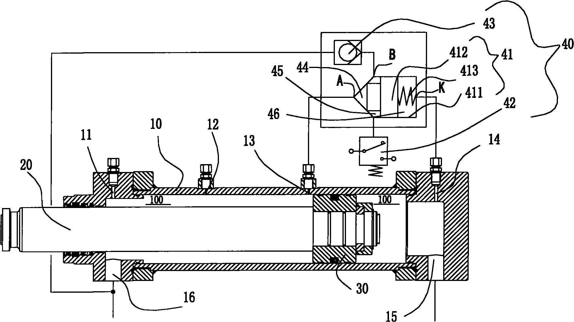
[0025] Such as figure 1 As shown, the hydraulic cylinder device of the present invention includes a cylinder 10, a piston 30 that performs reciprocating linear motion in the cylinder 10, a piston rod 20 that is connected to the piston 30 at one end and extends out of the cylinder 10 at the other end, and a differential pressure electric signal to generate device 40.

[0026] Two ends of the cylinder 10 are respectively formed with an oil inlet and outlet 15 and 16 .

[0027] Both ends of the cylinder 10 have a piston movement intended control area 100. When the piston 30 moves to the piston movement intended control area 100, it is necessary to perform control operations such as buffering or reversing on the movement of the piston 30, each described A differential pressure electrical signal generating device 40 of the present invention is correspondingly provided in the piston motion intended control area 100 (only one differential pressure electrical signal generating device...

no. 2 example

[0041] In the second embodiment, the same reference numerals will be used to designate the same or similar components as much as possible.

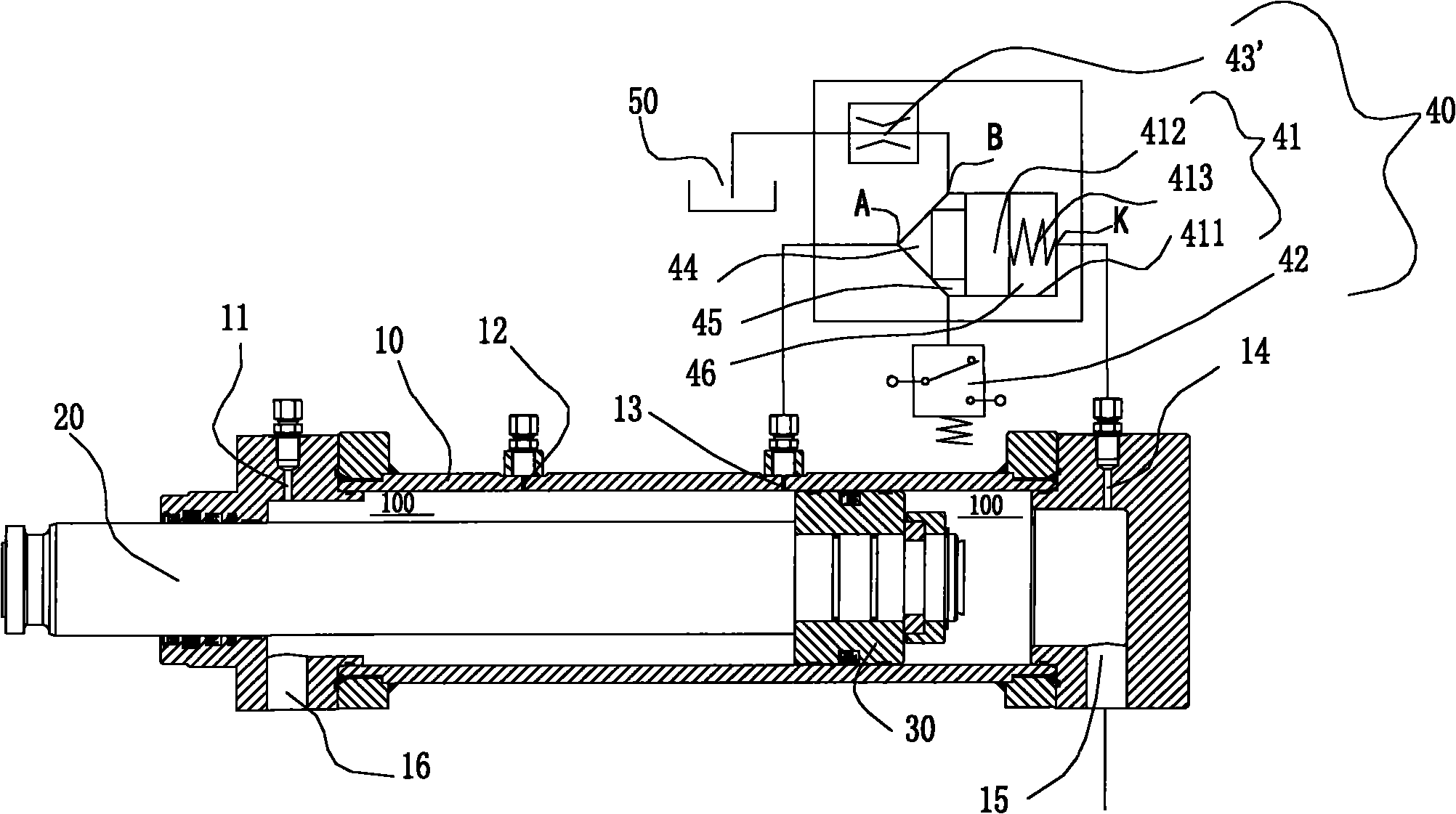
[0042] Such as figure 2 As shown, the structure of the second embodiment of the present invention is basically the same as that of the first embodiment of the present invention, the difference between the two is that the one-way valve 43 in the first embodiment is replaced by a damper 43', and the damper The oil drain end of 43' is directly connected to an oil tank 50 by a pipeline. In this embodiment, since the oil drain end of the damper 43' is connected to an oil tank 50 by a pipeline, the pipeline communicating with the oil inlet and outlet 16 on the other side of the cylinder 10 in the first embodiment can be omitted.

[0043] The working process of the second embodiment will be briefly described below.

[0044] When the piston 30 has not yet moved into the intended control area 100 of the piston movement, the signal oil holes 13 ...

no. 3 example

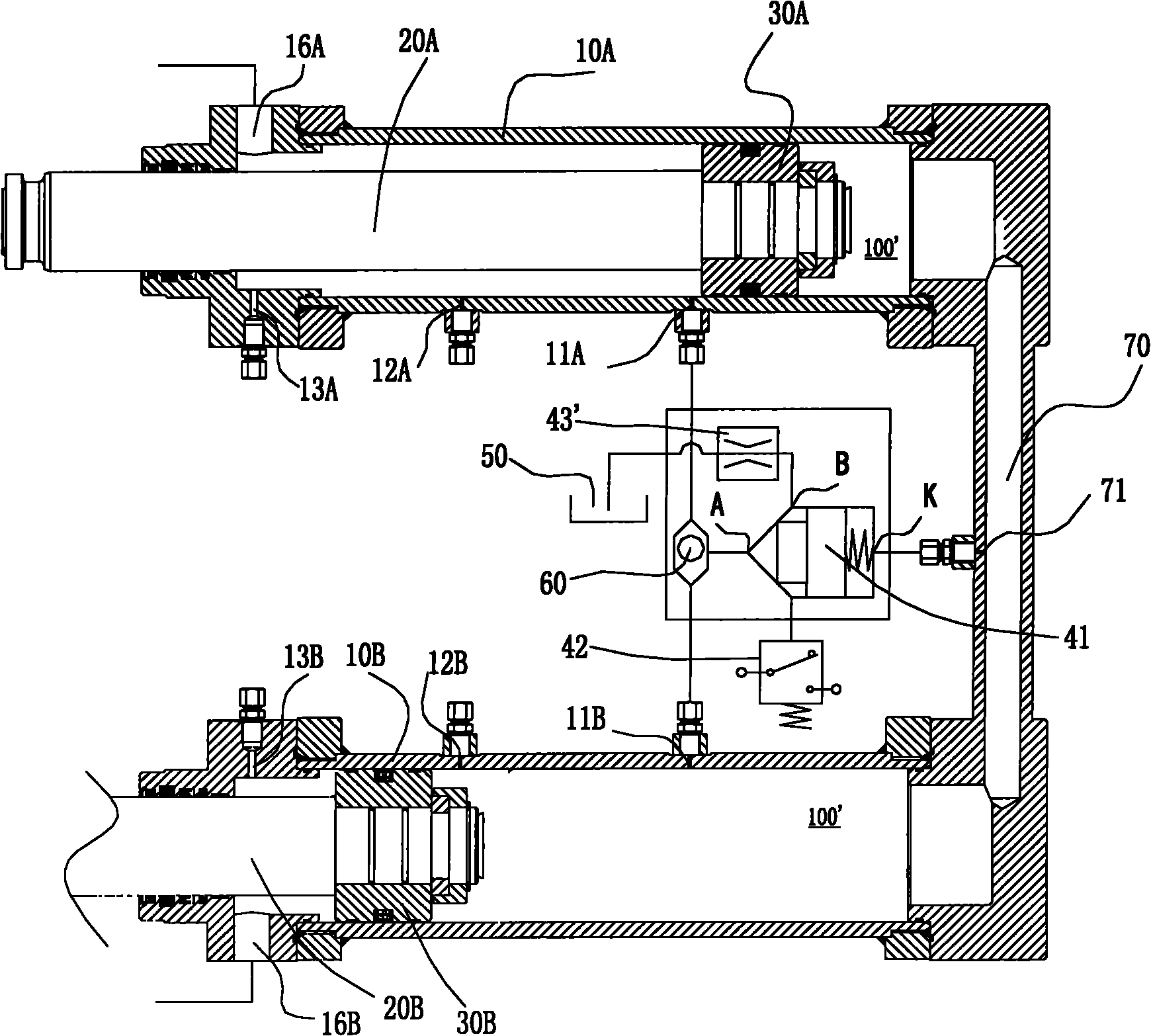
[0048] Such as image 3 As shown, the hydraulic cylinder device according to the third embodiment of the present invention includes a first hydraulic cylinder, a second hydraulic cylinder connected in series with the first hydraulic cylinder, and a differential pressure electric signal generating device.

[0049] The first hydraulic cylinder includes: a cylinder barrel 10A, a piston 30A that performs linear reciprocating motion in the cylinder barrel 10A, and a piston rod 20A that is connected to the piston 30A at one end and extends out of the cylinder barrel 10A at the other end. At the beginning of the piston stroke of the cylinder 10A (ie image 3 The left-hand end of the middle) is formed with a first oil inlet and outlet port 16A, at the end of the piston stroke of the cylinder 10A (ie image 3 There is a piston motion control area 100' at the right-hand end of the center), and a first signal oil hole 11A penetrating through the cylinder wall of the cylinder barrel 10A ...


PUM


Abstract

The invention discloses a hydraulic cylinder device, which comprises a cylinder barrel, a piston, a piston rod and a differential pressure electric signal generating device, wherein two ends of a piston movement simulated control zone of the cylinder barrel respectively form signal oil holes, and the differential pressure electric signal generating device comprises a differential pressure valve, an oil draining device and a pressure sensor. When the piston does not enter the piston movement simulated control zone, a valve core closes the differential pressure valve under the propping of an elastic component, so that an executing cavity and a differential pressure detection cavity of the differential pressure valve are separated from each other; and when the piston enters the piston movement simulated control zone, the valve core overcomes the propping force of the elastic component to open the differential pressure valve under the differential pressure action of the two ends of the piston, so that the executing cavity and the differential pressure detection cavity are communicated with each other. The hydraulic cylinder device has good stability and high pressure resistance capability and pressure pulse resistance capability.

Description

technical field [0001] The invention relates to a hydraulic oil cylinder with a structure capable of detecting the position of the piston movement of the oil cylinder and controlling the movement (reversing, buffering, etc.) of the oil cylinder by converting the hydraulic pressure difference signal into an electric signal. Background technique [0002] Generally speaking, a traditional hydraulic cylinder device includes a cylinder, a piston that reciprocates linearly in the cylinder, and a piston rod that is connected to the piston at one end and extends out of the cylinder at the other end. The two ends of the working cavity inside the cylinder are the quasi-control area of ​​the piston movement. When the piston moves to the quasi-control area of ​​the piston movement, the movement of the piston (including reversing and buffering) needs to be controlled. [0003] At present, in mechanical equipment such as hydraulic cylinder reciprocating pumping (such as: concrete pumping ...

Claims


Application Information

Patent Timeline
Patent Type & Authority Applications(China)
IPC IPC(8): F15B15/14F15B15/28
Inventor 张戚谢恒星刘洪庆吴富国
Owner 中集车辆(江门市)有限公司
Why Eureka
Try Eureka