Method for measuring and calculating temperature of effluent and drain from heater with steam cooler and drain cooler of steam engine

A technology of hydrophobic temperature and water outlet temperature, which is applied in the temperature measurement of moving fluids, etc. It can solve the problems of inability to calculate heat transfer coefficient, high measurement cost, inconvenient repair and maintenance, etc.

Inactive Publication Date: 2010-10-06
SOUTHEAST UNIV
View PDF2 Cites 5 Cited by
  • Summary
  • Abstract
  • Description
  • Claims
  • Application Information

AI Technical Summary

Problems solved by technology

[0003] At present, in the thermal power plant's plant-level monitoring information system SIS (Supervisory Information System) or system distributed control system DCS (Distribution Control System), for the regenerative heater with steam cooler and drain cooler, although there are outlet water and Drainage temperature measurement points, but due to poor operating conditions and weak maintenance and other reasons, the measurement reliability is generally poor. In addition, the conventional measurement method of the water side temperature of the heater still has the following deficiencies: First, in thermal power unit thermal measurement In the system, a thermal resistance sensor is often used to monitor the outlet water temperature of the regenerative heater, and the correspondi

Method used


Image

  • Method for measuring and calculating temperature of effluent and drain from heater with steam cooler and drain cooler of steam engine
  • Method for measuring and calculating temperature of effluent and drain from heater with steam cooler and drain cooler of steam engine
  • Method for measuring and calculating temperature of effluent and drain from heater with steam cooler and drain cooler of steam engine

Examples


Embodiment Construction

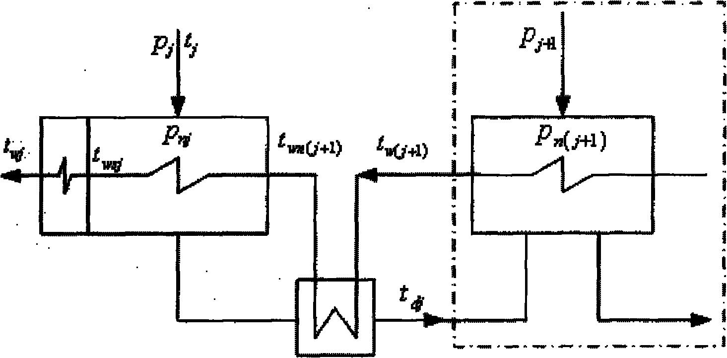
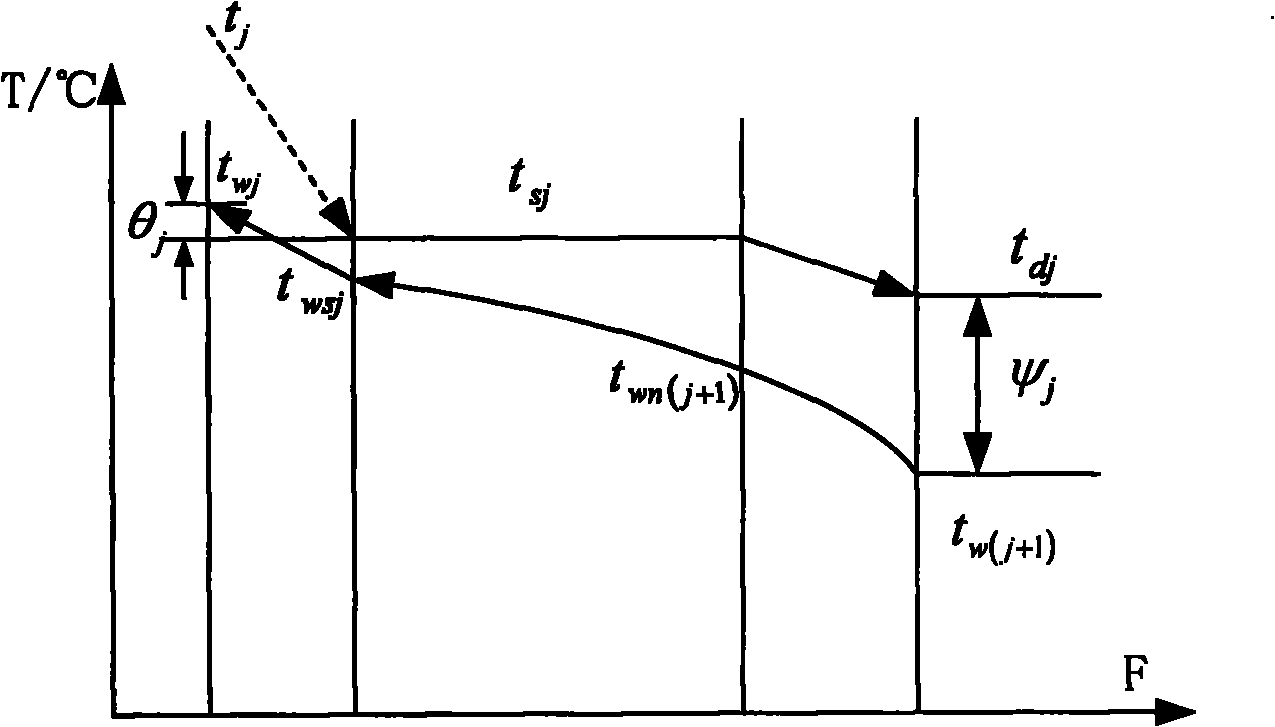
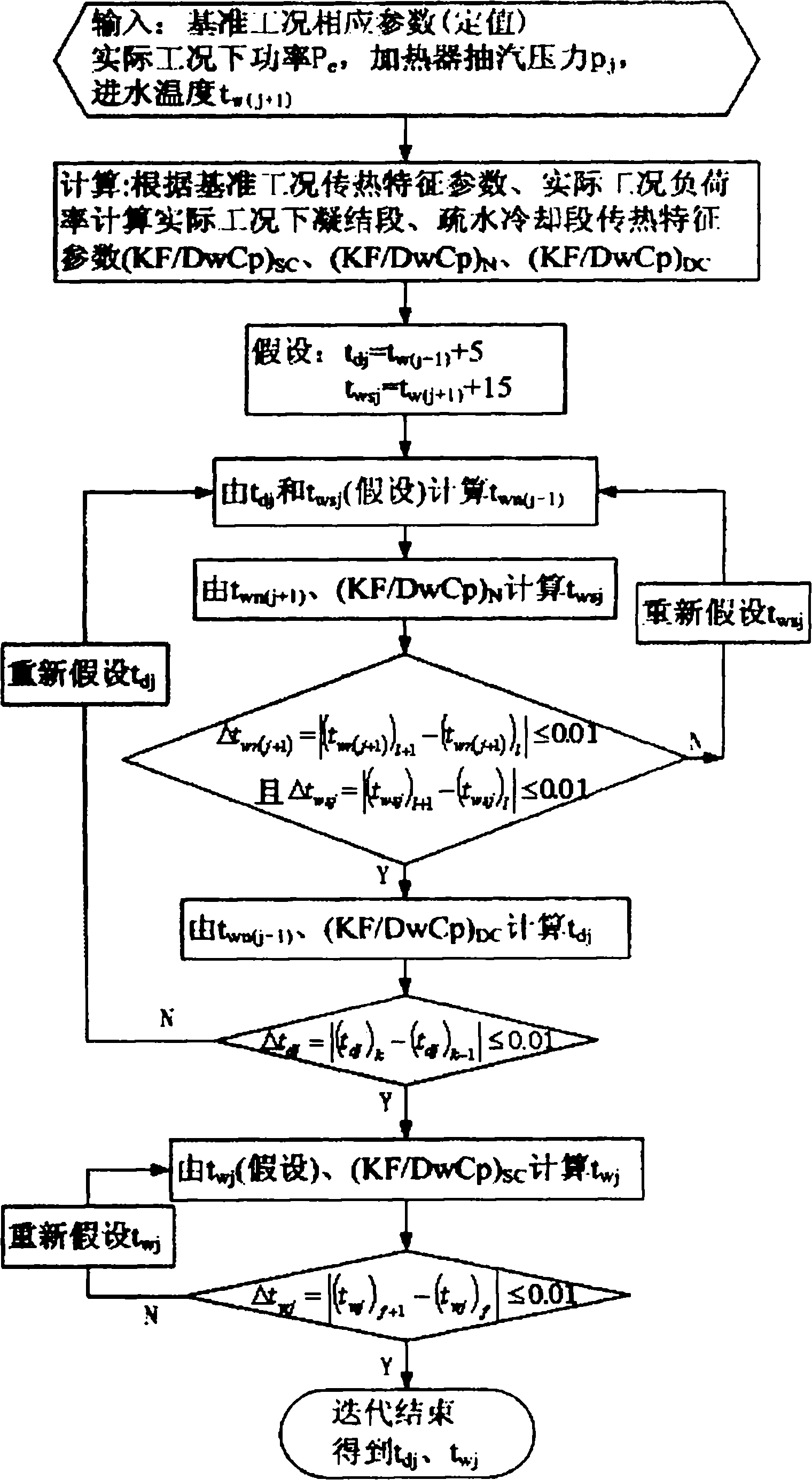
[0086] A method for measuring and calculating the outlet water and drainage temperature of a heater with a steam-cooling and cooling-draining device in a steam turbine, characterized in that, step 1: calculate the temperature t of the intermediate transition point between the steam cooling section and the pure condensation section of the heater under the reference working condition wsj o and the intermediate transition point temperature t between the pure condensation section and the hydrophobic cooling section wn(j+1) o :

[0087] Select the rated power design condition (or performance assessment test condition) of the unit as the reference condition, and the parameter marked with the letter "o" indicates that it is the parameter under the reference condition. And select the thermal parameters of the jth-stage heater under the reference condition: shell side pressure p nj o , extraction steam temperature t j o , hydrophobic temperature t dj o , outlet water temperatur...


PUM


Abstract

The invention relates to a method for measuring and calculating the temperature of effluent and drain from a heater with a steam cooler and a drain cooler of a steam engine. The method comprises the following steps: selecting machine set design conditions or performance test conditions as standard conditions, and selecting thermal parameters of the heater under the standard conditions, wherein the thermal parameters comprise shell side pressure, steam extracting temperature, drain temperature, effluent temperature, water inlet temperature and power of the machine set; calculating the heat transmission characteristic coefficients of a steam cooling section, a pure condensation section and a drain cooling section of the heater under the standard conditions; reading or calculating the shell side pressure, the steam extracting temperature, the water inlet temperature of the heater and the power of the machine set under the actual conditions from the database of a supervisory information system(SIS) or a decentralized control system (DCS) in a heat-engine plant; calculating to obtain the heat transmission characteristic coefficients of the pure condensation section of the heater under the actual conditions; carrying out iterative computations to obtain the actual middle transition temperature and the drain temperature of the steam cooling section and the pure condensation section; calculating to obtain the actual heat transmission characteristic coefficients of the steam cooling section of the heater; and finally carrying out iterative computations to obtain the effluent temperature.

Description

technical field [0001] The invention relates to a method for measuring and calculating parameters of a heater equipped with steam-cooling and cooling-draining devices in a steam turbine, in particular to a method for measuring and calculating the outlet water and drainage temperatures of a heater equipped with steam-cooling and cooling-draining devices in a steam turbine. Background technique [0002] With the continuous improvement of parameters and capacity of thermal power units, improving the performance of the regenerative system to improve the operating economy of the unit has attracted increasing attention. The measurement of the outlet water and drainage temperature of the regenerative heater plays an important role in the calculation of the heat balance of the regenerative system, monitoring and optimization of the unit performance, so it is necessary to monitor it online. So far, there is no report on the method for measuring the outlet water and drainage temperatu...

Claims


Application Information

Patent Timeline
IPC IPC(8): G01K13/02
Inventor 王培红王泉许寅李兵殷捷
Owner SOUTHEAST UNIV
Why Eureka
Try Eureka