Measuring system and method of low-speed non-linear seepage parameters

A measurement system and nonlinear technology, which is applied in the field of testing the permeability of porous materials, can solve the problems of low-speed nonlinear seepage curve, which cannot be drawn, the price is expensive, and the operation process is complicated, so as to avoid the problem of unreliable measurement results and pressure measurement results. The effect of accurate and simplified measurement structure

Inactive Publication Date: 2011-09-14
CHINA UNIV OF PETROLEUM (BEIJING)
View PDF1 Cites 2 Cited by
  • Summary
  • Abstract
  • Description
  • Claims
  • Application Information

AI Technical Summary

Problems solved by technology

Therefore, the experimental data has high requirements for measurement accuracy, and it is difficult for ordinary pressure and flow measurement equipment to meet the requirements
If you purchase professional experimental equipment, it is generally expensive, the operation process is complicated, and it is easy to be damaged. In the actual use process, it is difficult to show the superiority of such professional equipment
Judging from the published patent document CN200610069507.8 at home and abroad, the measurement method of the quasi-thrust pressure gradient has been relatively perfect, but the "flow velocity-pressure gradient" relationship (ad curve) in the lower pressure range cannot be accurately measured or even cannot be measured. Moreover, there is no measurement method for the threshold pressure (point a) of low-permeability porous media
Therefore, the complete low-velocity nonlinear seepage curve in low-permeability porous media cannot be drawn, which restricts the development of low-velocity nonlinear seepage theory

Method used


Image

  • Measuring system and method of low-speed non-linear seepage parameters
  • Measuring system and method of low-speed non-linear seepage parameters
  • Measuring system and method of low-speed non-linear seepage parameters

Examples


Embodiment 1

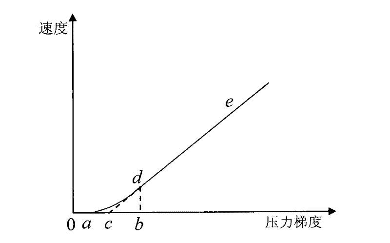
[0046] Embodiment 1 of the present invention provides a measurement system for low-speed nonlinear seepage parameters, so as to realize the measurement of pressure and fluid volume under low-speed nonlinear seepage conditions. The measurement system of the embodiment of the present invention is mainly applied to the measurement of pressure (including start-up pressure) and fluid volume under low-speed nonlinear conditions, and draws the "flow velocity-pressure gradient" curve of low-permeability porous media according to the measurement results.

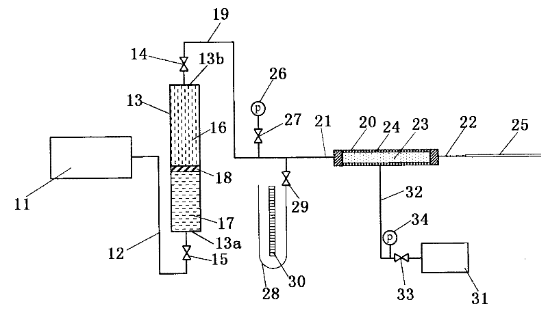
[0047] figure 2 It is a structural block diagram of a measurement system for low-speed nonlinear seepage parameters in Embodiment 1 of the present invention. The structure and function of the measurement system are described in detail below, such as figure 2 As shown, the measurement system includes:

[0048] The intermediate container 13 has a first opening 13a and a second opening 13b, and is hollow inside to accommodate the di...

Embodiment 2

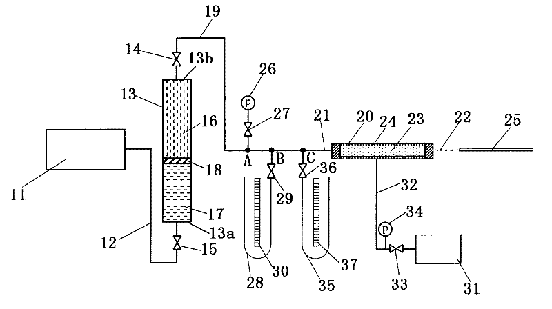
[0073] image 3 It is a structural block diagram of another measurement system for low-speed nonlinear seepage parameters in Embodiment 2 of the present invention. image 3 measurement system with figure 2 Compared with the measurement system of , the difference is that, image 3 The medium pressure measurement device is a 3-stage pressure monitoring device based on the pressure gauge 26 , the first U-shaped tube pressure gauge 28 and the second U-shaped tube pressure gauge 35 . The above differences will be described in detail below, and the similarities will not be repeated.

[0074] see image 3 , the pressure measuring device comprises: a pressure gauge 26, a first U-shaped tube manometer 28 and a second U-shaped tube manometer 35, the range of the pressure gauge 26 is greater than the range of the first U-shaped tube manometer 28, so The range of the first U-shaped tube manometer 28 is greater than the range of the second U-shaped tube manometer 35;

[0075] The pre...

Embodiment 3

[0090] Figure 4 It is a structural block diagram of another measurement system for low-speed nonlinear seepage parameters in Embodiment 3 of the present invention. Figure 4 The measurement system shown with image 3 Compared to the measurement system shown, the difference is that, Figure 4 Medium flow measurement devices are multi-stage flow monitoring devices based on multiple capillary flowmeters. The above differences will be described in detail below, and the similarities will not be repeated.

[0091] Figure 4 The multi-stage flow monitoring device includes: at least two capillary flowmeters of different specifications, and a switch part is respectively arranged on the pipeline connecting each capillary flowmeter with the fourth opening 22 of the core holder 20 .

[0092] Therefore, according to the pressure at the inlet end of the core holder 20 , one of the at least two switch parts can be opened to activate the capillary flowmeter of the corresponding specifica...


PUM


Abstract

The embodiment of the invention provides measuring system and method of low-speed non-linear seepage parameters. The system comprises a power output device, a pressure measuring device and a flow measuring device, wherein the power output device is connected with a first opening of an intermediate container through a pipeline and is used for outputting different drive pressures so as to displace a displacing fluid in the intermediate container to be transmitted to a core of a core holder by the pipeline; the pressure measuring device comprises a pressure gage and a U-shaped pipe pressure gagewhich are respectively connected with a third opening of the core holder through pipelines and is used for measuring the pressure of the third opening of the core holder under different drive pressures; the U-shaped pipe pressure gage can display the level height difference so as to acquire the starting pressure of the core when the drive pressure is reduced to the minimum value, a switching partis in a closed state and the self level is stable; and the flow measuring device is connected with a fourth opening of the core holder through a pipeline and is used for measuring the volume of the displacing fluid seeped from the core under the different pressures of the third opening. The system can accurately measure the pressure, the starting pressure and the fluid volume under the low-speed non-linear seepage conditions.

Description

technical field [0001] The invention relates to the technical field of testing the permeability of porous materials, in particular to a measurement system and method for low-speed nonlinear seepage parameters. Background technique [0002] Low velocity non-linear fluid flow is a special phenomenon when fluid flows in low permeability porous media. This phenomenon widely exists in oil and gas field development engineering, geotechnical engineering, hydraulic engineering and industrial catalysis and other related disciplines. Seepage in low-permeability porous media no longer obeys Darcy's Law. The shape of the characteristic curve of low-speed nonlinear seepage is closely related to fluid type, rock type and fluid saturation; the seepage capacity of fluid in porous media is a continuous function of pressure. figure 1 It is a schematic diagram of a typical nonlinear seepage characteristic curve of a low-permeability porous medium drawn according to the method of the prior ar...

Claims


Application Information

Patent Timeline
Patent Type & Authority Patents(China)
IPC IPC(8): G01N15/08
Inventor 程林松曾保全李春兰郝斐郑华
Owner CHINA UNIV OF PETROLEUM (BEIJING)
Why Eureka
Try Eureka