Piezoresistive monolithic integrated tri-axial acceleration sensor and manufacturing method thereof

A monolithic integration, axial acceleration technology, applied in the direction of acceleration measurement using inertial force, piezoelectric/electrostrictive/magnetostrictive devices, impedance network, etc., can solve the problem of large volume, low accuracy of vector measurement, and misalignment of centroids And other issues

Inactive Publication Date: 2010-10-06
NO 49 INST CHINESE ELECTRONICS SCI & TECH GRP
View PDF0 Cites 9 Cited by
  • Summary
  • Abstract
  • Description
  • Claims
  • Application Information

AI Technical Summary

Problems solved by technology

[0003] The present invention proposes a piezoresistive monolithic accelerometer in order to solve the shortcomings of low vector measurement accuracy, poor reliability, non-coincidence of centroids, and large volume that exist in the measurement of the three-axis accelerometers currently designed using various principles. Integrated triaxial acceleration sensor and manufacturing method

Method used


Image

  • Piezoresistive monolithic integrated tri-axial acceleration sensor and manufacturing method thereof
  • Piezoresistive monolithic integrated tri-axial acceleration sensor and manufacturing method thereof
  • Piezoresistive monolithic integrated tri-axial acceleration sensor and manufacturing method thereof

Examples


specific Embodiment approach 1

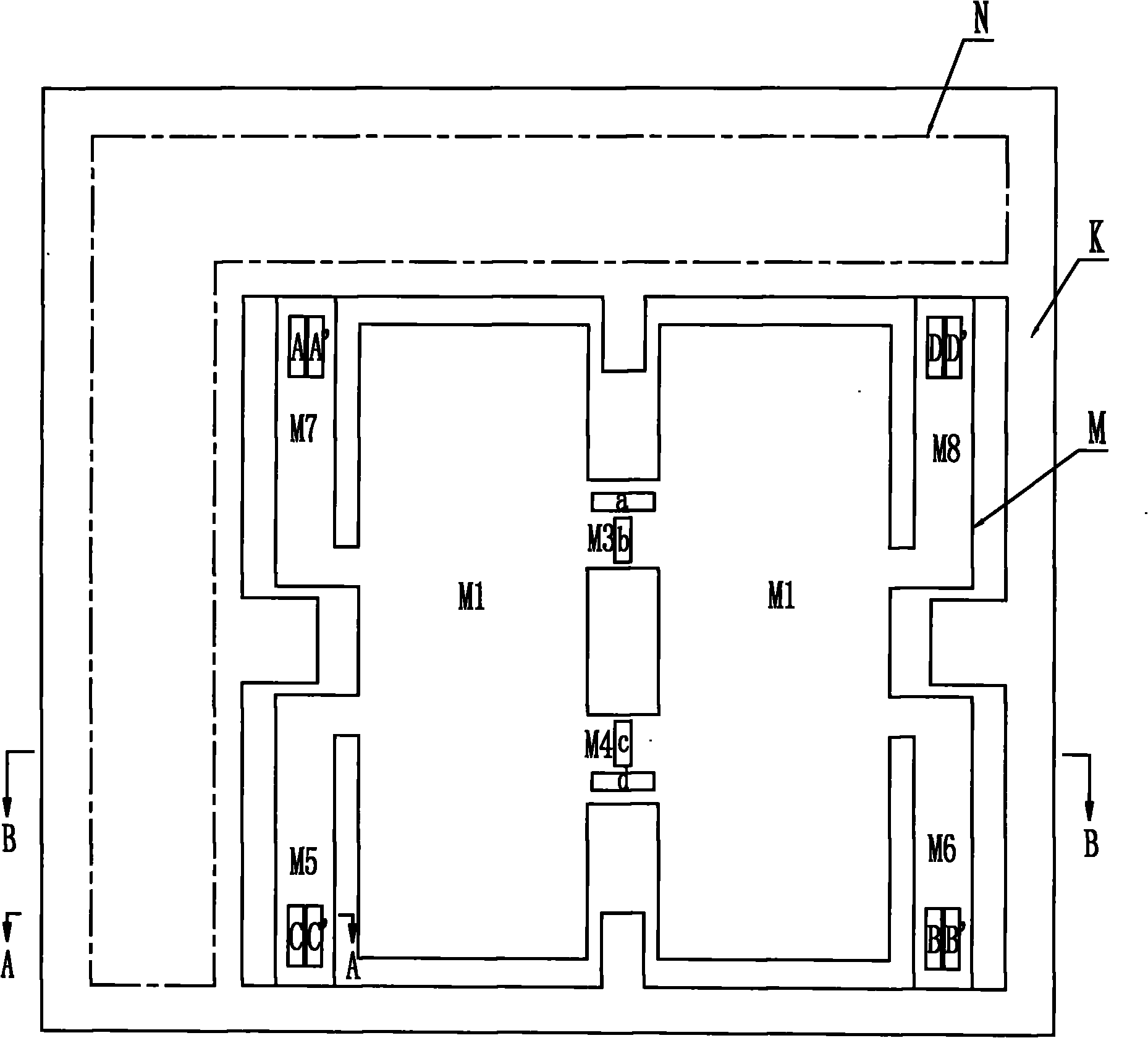
[0036] Specific implementation mode one: combine figure 1 and Figure 20 Describe the present embodiment, the piezoresistive monolithic integrated three-axis acceleration sensor of the present embodiment is integrated by a chip, and the chip is divided into fixed support frame area K, circuit area N and sensing area M; Sensing area M is formed by the first Mass M1, second mass M2, first intermediate beam M3, second intermediate beam M4, first to fourth L-shaped sensitive beams M5, M6, M7, M8 and first to twelfth piezoresistors A, Composed of A', B, B', C, C', D, D', a, b, c, d; the first mass M1 and the second mass M2 are arranged symmetrically along the longitudinal central axis of the sensing area M, The two sides between the first mass M1 and the second mass M2 are connected by two first intermediate beams M3 and the second intermediate beam M4, and the two sides between the first mass M1 and the second mass M2 Two L-shaped sensitive beams are respectively arranged on the...

specific Embodiment approach 2

[0037] Specific implementation mode two: combination figure 1 and Figure 20 This embodiment is described. The difference between this embodiment and the first embodiment is that two longitudinal limit blocks are respectively provided in the two gaps between the first mass M1 and the second mass M2. Other compositions and connection methods are the same as those in Embodiment 1. The purpose of setting two longitudinal limit blocks is to realize the overload protection for the acceleration in the x-axis direction.

specific Embodiment approach 3

[0038] Specific implementation mode three: combination figure 1 and Figure 20 Describe this embodiment, the difference between this embodiment and specific embodiment 1 or 2 is that the gap between the first L-shaped sensitive beam M5 and the second L-shaped sensitive beam M6 is different from the third L-shaped sensitive beam M7 and the fourth L-shaped sensitive beam M7. Two transverse limit blocks are respectively arranged in the gaps between the type-sensitive beams M8. Other compositions and connection modes are the same as those in Embodiment 1 or 2. The purpose of setting two lateral limit blocks is to realize the overload protection for the acceleration in the y-axis direction.


PUM

PropertyMeasurementUnit
Thicknessaaaaaaaaaa
Thicknessaaaaaaaaaa
Thicknessaaaaaaaaaa

Abstract

The invention provides a piezoresistive monolithic integrated tri-axial acceleration sensor and a manufacturing method thereof, relating to the field of a piezoresistive acceleration sensor, and overcoming the defects of low vector measurement precision, bad reliability, misaligned barycenter and large volume during measuring. The sensor is integrated by a chip, and the chip is divided into a fixed frame supporting zone, a circuit zone and a sense zone; and two first weight blocks are symmetrically arranged along the lengthways axial wire of the sense zone, two first middle beams are connected between the two first weight blocks, the outer surfaces of the two first weight blocks are respectively provided with two L-shaped sensitive beams, a first L-shaped sensitive beam to a forth L-shaped sensitive beam are symmetrically arranged relative to the transverse axial wire and the lengthways axial wire of the sense zone, a first piezoresistor to a eighth piezoresistor are arranged on heads of the sensitive beams, a ninth piezoresistor to a twelfth piezoresistor are arranged on the two first middle beams, and the upper surface of the chip is positioned on the same horizontal plane and is sequentially to be the beams, the weight blocks and the outer part of the sensitive zone from the deep to the shallow. With the principle of piezo-resistance effect, the invention integrates an accelerometer with a circuit on one chip, thereby improving the measuring precision and the reliability.

Description

technical field [0001] The invention relates to the field of piezoresistive acceleration sensors. Background technique [0002] Common micro-accelerometer products are mainly single-axis, while micro-inertial systems and other applications often require two-axis or three-axis accelerometers to detect acceleration vectors. In order to meet the needs of multi-axis detection, three single-axis accelerometers are usually used The combined use of axial accelerometers will lead to the disadvantages of low vector measurement accuracy, poor reliability, non-coincidence of centroids, and large volume. There have been some literature reports on the development of multi-axis micro-accelerometer devices. The three-axis accelerometer designed using the piezoelectric principle has the disadvantages of low precision and poor stability; the three-axis accelerometer designed using the capacitance principle has signal processing difficulties. The disadvantage of poor process compatibility. ...

Claims


Application Information

Patent Timeline
IPC IPC(8): G01P15/12B81B7/02
Inventor 田雷付博王永刚李海博寇文兵金建东齐虹李玉玲王晓光王振王江张岩
Owner NO 49 INST CHINESE ELECTRONICS SCI & TECH GRP
Why Eureka
Try Eureka