Novel automatic feed plate cutting mechanism

An automatic feeding and shearing technology, which is applied in the direction of shearing devices, shearing machine equipment, shearing machine accessories, etc., can solve the problems of low precision, low labor efficiency, troublesome cutting width adjustment, etc., and achieve high adjustment accuracy , high labor productivity, and the effect of reducing labor intensity

Inactive Publication Date: 2010-10-13
王玲
View PDF0 Cites 21 Cited by
  • Summary
  • Abstract
  • Description
  • Claims
  • Application Information

AI Technical Summary

Problems solved by technology

[0003] The purpose of the present invention is to provide a new type of automatic feeding shearing mechanism, which solves the troublesome adjustment of the shearing width and low precision of the existing shearing machine due to structural factors, and at the same time, also overcomes the existence of the existing shearing machine due to the inability to automatically feed materials. The defects of low labor efficiency and high labor intensity of workers

Method used


Image

  • Novel automatic feed plate cutting mechanism
  • Novel automatic feed plate cutting mechanism

Examples


Embodiment Construction

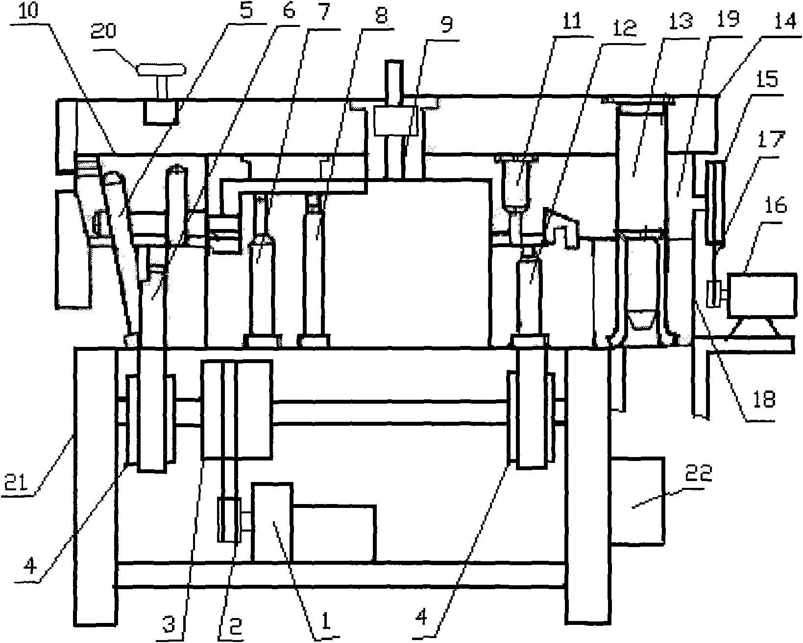
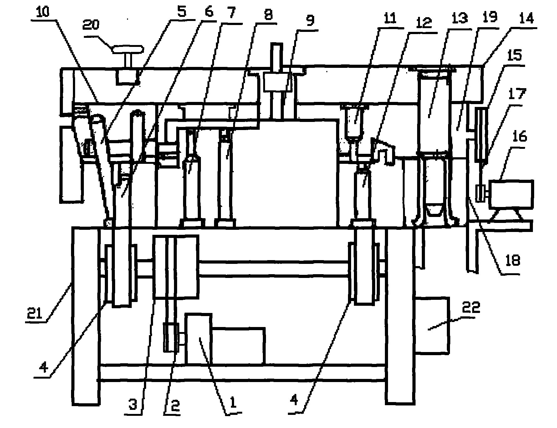
[0008] The present invention will be described in detail below in conjunction with the accompanying drawings.

[0009] The present invention consists of a reducer (1), a crank slider mechanism, a press-lift roller mechanism, an upper shaft roller (11), a lower shaft roller (12), a stepping motor (16) and a program controller (22). (1) Connected with the motor, the reducer (1) transmits the motion of the motor to the main shaft through the motor pulley (2) and the large pulley (3), and a pair of eccentric wheels (4) in the crank slider mechanism are fixed on At both ends of the main shaft, the eccentric wheel (4) drives the upper knife rest (10) through the connecting rod, and the upper knife rest (10) then reciprocates up and down, and the pressing mechanism is connected with the upper knife rest (10). The material plate (7) and the stage clip (9) are composed, the stepper motor (16) drives the lower shaft roller (12) through the sprocket (15), the stepper motor (16) is contro...


PUM


Abstract

The invention relates to a novel automatic feed plate cutting mechanism, which consists of a speed reducer, a crank block mechanism, a press-lift roller mechanism, an upper shaft roller, a lower shaft roller, a stepping motor and a programming controller, wherein the speed reducer is connected with the motor and transmits the motion of the motor to a main shaft component through a belt wheel and a large belt wheel of the motor; a pair of eccentric wheels in the crank block mechanism is fixed at both ends of a main shaft; the eccentric wheels drive a top rest through a connecting rod, so that the top rest reciprocates up and down; a pressure feeding mechanism is connected with the top rest, and consists of a pressure plate and a pressure spring; the stepping motor drives the lower shaft roller through a chain wheel, and is controlled by the programming controller; and both ends of the lower shaft roller and the upper shaft roller are engaged by a gear set. In the press-lift roller mechanism, an adjustable slide block is driven by an adjusting screw rod to ascend and descend, so that the upper shaft roller and the lower shaft roller maintain an appropriate gap; and plate materials are pressed and loosened by using the pressure plate, and simultaneously, the plate materials are convenient to feed.

Description

technical field [0001] The invention relates to an automatic feeding shearing mechanism, in particular to a novel automatic feeding shearing mechanism, which belongs to the technical field of stamping equipment. Background technique [0002] At present, when the shearing machine cuts the metal sheet, the width of the shearing material is determined by the stopper set behind the cutter of the shearing machine. During operation, the distance between the stopper and the knife edge is adjusted in advance to determine the shearing width. At the same time, the feeding of materials is manual feeding, so this kind of shearing machine is not only troublesome to adjust, but also has low adjustment accuracy. In addition to manual feeding, the labor efficiency is low and the labor intensity of workers is high. Contents of the invention [0003] The purpose of the present invention is to provide a new type of automatic feeding shearing mechanism, which solves the troublesome adjustment...

Claims


Application Information

Patent Timeline
Patent Type & Authority Applications(China)
IPC IPC(8): B23D15/06B23D15/08B23D15/12B23D33/02B21D43/02
Inventor 王玲
Owner 王玲
Why Eureka
Try Eureka