Material transfer method and transfer device

A transfer device and material technology, applied in the direction of conveyor objects, transportation and packaging, etc., can solve the problems of material spreading, cutting tape, tape deviation, etc., and achieve the effect of reducing wear, avoiding being torn, and preventing deviation

Active Publication Date: 2010-10-20
HUADIAN HEAVY IND CO LTD
View PDF4 Cites 18 Cited by
  • Summary
  • Abstract
  • Description
  • Claims
  • Application Information

AI Technical Summary

Problems solved by technology

In the past, material transfer usually uses a chute with a rectangular cross-section to connect between the feeding belt conveyor and the receiving belt conveyor. The landing point on the tape often shifts to both sides of the tape, causing the tape to deviate and scatter during operation; when the drop between the feeding tape machine and the receiving tape machine is large and the material is highly abrasive , There are many problems in this way

Method used


Image

  • Material transfer method and transfer device
  • Material transfer method and transfer device
  • Material transfer method and transfer device

Examples


Embodiment 1

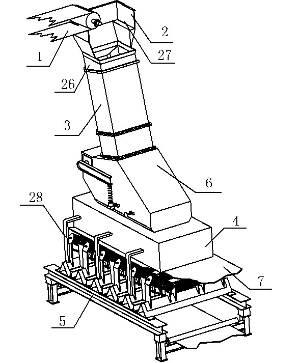
[0039] Embodiment 1 of the present invention: a material transfer device for reloading small granular materials, its structure is as follows figure 1 As shown; including feeding belt machine 1, unloading funnel 2, guide material centering chute 3, material guide trough 4, material receiving buffer device with pallet 5, material receiving belt 7; unloading funnel 2 and guide material centering chute 3 are connected, the lower part of the centering chute 3 is inserted into the guide trough 4, and the guide trough 4 is placed on the receiving buffer device 5 with a pallet, and the feed trough 4 is connected with the receiving buffer device 5 with a pallet through the connecting frame 28. The material buffer device 5 is connected, and the buffer fork 6 conveys the material to the material receiving tape 7 on the material receiving belt machine.

[0040] The front plate and both side plates of the unloading funnel 2 are provided with a stacking mechanism 8; the stacking mechanism 8...

Embodiment 2

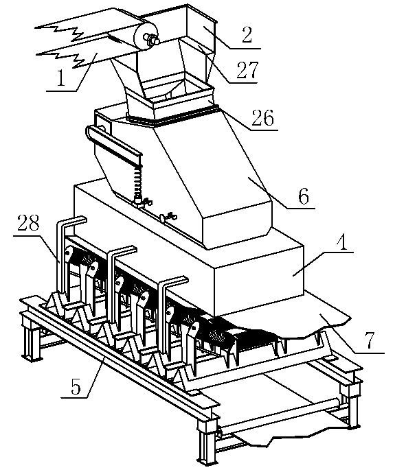
[0045] Embodiment 2 of the present invention: be used for reprinting bulk material, as: the transfer device of coal etc., comprise feeding tape conveyor 1, unloading funnel 2, guide chute 4, the material receiving buffer device 5 with supporting plate, buffer Fork 6, material receiving tape 7; unloading funnel 2 is connected with middle funnel 26, and middle funnel 26 is connected with buffer fork 6, and the bottom of buffer fork 6 is inserted in feed channel 4, and feed guide channel 4 is a closed metal box. The material guide trough 4 is placed on the material receiving buffer device 5 with a pallet, the material guide trough 4 is connected with the material receiving buffer device 5 with a pallet through the connecting frame 28, and the buffer fork 6 conveys the material to the material receiving device on the material receiving belt conveyor. Tape 7 on.

[0046] The front plate and the two side plates of the unloading funnel 2 are provided with a stacking mechanism 8;

[...

Embodiment 3

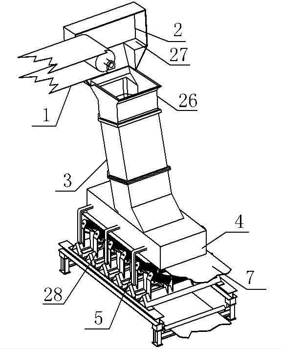
[0050] Embodiment 3 of the present invention: a material transfer device, used for reprinting small pieces of material, such as sand and stones; it includes a feeding tape machine 1, an unloading funnel 2, a material guide centering chute 3, a material guide trough 4, Material receiving buffer device 5 with pallet, buffer fork 6, material receiving tape 7; unloading funnel 2 is connected with middle funnel 26, middle funnel 26 is connected with guide centering chute 3, guide material centering chute 3 is connected with buffer fork 6 are connected, the lower part of the buffer fork 6 is inserted into the material guide trough 4, the material guide trough 4 is a closed metal box, the material guide trough 4 is placed on the receiving buffer device 5 with a pallet, the material guide trough 4 passes The connecting frame 28 is connected with the material-receiving buffer device 5 with a pallet, and the buffer fork 6 conveys the material to the material-receiving tape 7 on the mater...


PUM


Abstract

The invention discloses a material transfer method and a used material transfer device. Materials are accumulated on a discharge hopper to form a material storage area; when the materials are accumulated fully, the materials overflow and slide downwards into a material guide centering chute, enter a buffer fork through the material guide centering chute, and are accumulated on a fork plate to form a storage area; and then the materials are continuously conveyed to a material guide groove, and finally conveyed to a receiving adhesive tape on a receiving buffer device with a support plate. Because the discharge hopper with the material storage area, the buffer fork and the material guide centering chute with a groove-shaped receiving bearing surface are used, the materials are accumulated on the discharge hopper and the buffer fork to a material accumulation layer, and the subsequent materials are well buffered and centralized on the middle part of the adhesive tape so as to effectivelyreduce the abrasion of equipment caused by the materials and prevent the adhesive tape from deflecting and scattering the materials; and meanwhile, the receiving buffer device with the support plate is used below the receiving adhesive tape so that the materials are supported by the anti-tearing support plate when falling from the upside and the adhesive tape is prevented from being torn.

Description

technical field [0001] The invention relates to a material transfer method and a transfer device, which are particularly suitable for the transfer and transfer of highly abrasive materials such as iron ore, coke, and sand. Background technique [0002] At present, in industries such as mines, docks, building materials and electric power, belt conveyors are often used to transport materials. Due to various factors such as transportation mode and conveying direction, it is necessary to transfer materials on different belts or between different conveyors. In the past, material transfer usually uses a chute with a rectangular cross-section to connect between the feeding belt conveyor and the receiving belt conveyor. The landing point on the tape often shifts to both sides of the tape, causing the tape to deviate and scatter during operation; when the drop between the feeding tape machine and the receiving tape machine is large and the material is highly abrasive , There are ma...

Claims


Application Information

Patent Timeline
IPC IPC(8): B65G47/52
Inventor 刘天军李秀梅季浩宁刘伯宽刘皞王立波卢嘉树
Owner HUADIAN HEAVY IND CO LTD
Why Eureka
Try Eureka