Intelligent control method for hydraulic excavator

A hydraulic excavator, intelligent control technology, applied in the direction of mechanically driven excavator/dredger, program control, general control system, etc. Re-disassembly and other problems to achieve the effect of improving the control performance and operation ability, the default parameters are accurate and comprehensive, and the operation performance is improved

Inactive Publication Date: 2010-10-20
SANY HEAVY MACHINERY
View PDF5 Cites 19 Cited by
  • Summary
  • Abstract
  • Description
  • Claims
  • Application Information

AI Technical Summary

Problems solved by technology

[0004] However, the current control method cannot fully meet the individual needs of customers, which is reflected in:
[0005] 1) During the on-site use of the excavator, the customer cannot make custom settings according to the on-site working environment and personal operating habits. For example, when the site requires the handle to be pressed to the end, the rotation speed cannot exceed a certain value.
At present, it can only be realized by notifying the manufacturer, and the manufacturer sends engineers to modify the program. If the working environment is changed, it must be reset;
[0006] 2) When the excavator leaves the factory, the functions of the handle have been set. Due to the different habits of operators, some operators require to change the function of the handle, such as changing the operation mode of slewing and bucket excavation, which can only be disassembled and assembled again. pilot line;
[0007] 3) During the excavator development and design, calibration and debugging, and test detection, the working conditions of the simulated site are limited, so that the preset value set in the controller cannot reflect the actual complex operating conditions of the site and the real needs of customers, and the actual needs of the site Failure to provide timely and effective feedback to developers and designers

Method used


Image

  • Intelligent control method for hydraulic excavator
  • Intelligent control method for hydraulic excavator
  • Intelligent control method for hydraulic excavator

Examples


Embodiment 1

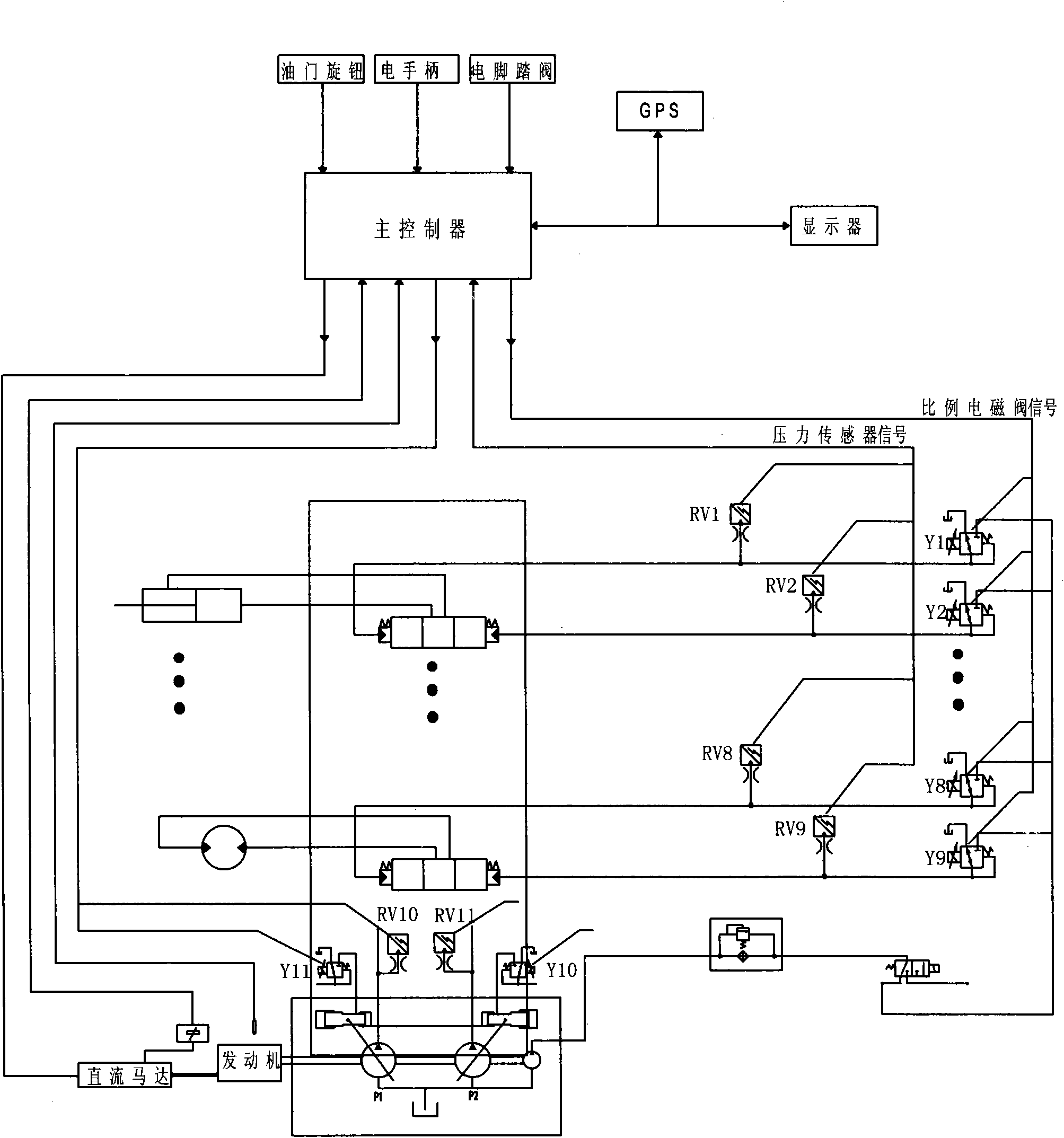
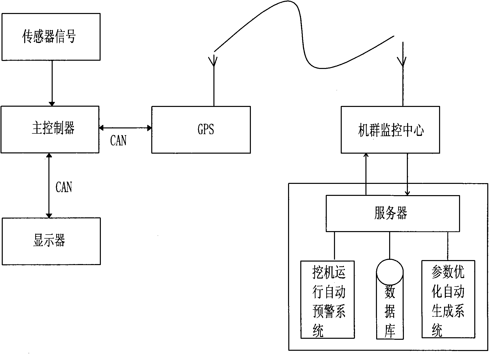
[0035] Embodiment one: see Figure 1~3As shown, an intelligent control method for a hydraulic excavator, the database set in the main controller is divided into a setting area and a recovery area, and the factory default data are stored in the setting area and the recovery area respectively, and the main controller Connect with the display modification interface through the CAN bus, the operation method is as follows:

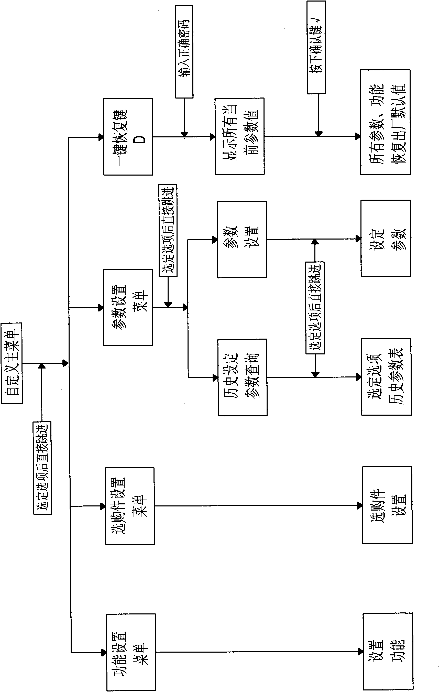
[0036] a. Data modification:

[0037] (1) The main controller detects data, such as figure 1 As shown, including handle signal, each pilot pressure sensor signal RV1~RV9 on the excavator, main pressure signals RV10, RV11 of the front and rear pumps, and ambient temperature sensor signal, the control parameters of the excavator and the adjustment range of the engine output power can be obtained through logical operation;

[0038] (2) The operator sets the control parameters of the excavator and the output power of the engine on the display modification interfa...


PUM


Abstract

The invention discloses an intelligent control method for a hydraulic excavator. The method is characterized in that: a database set in a main controller is divided into a setting area and a recovery area; and the main controller is connected with a display modification interface through a CAN bus, wherein the operation method of the main controller comprises the following steps of: a. data modification, namely (1) the main controller detects data and obtains regulating ranges of excavator control parameters and engine output power by a logical operation; (2) an operator sets the excavator control parameters and the engine output power in the regulating ranges; and (3) modified self-defining data is stored in the setting area through a CAN bus and an excavator operates according to the data; and b. data recovery, namely the main controller calls the data in a recovery area and covers the self-defining data in the setting area. In the intelligent control method for the hydraulic excavator, data regulating ranges are given according to detected data; and the operator can modify according to implementing working conditions and habits so as to meet the requirements on site environment and user control and contribute to improving the operating performance of the excavator.

Description

technical field [0001] The invention relates to an intelligent control method of a hydraulic excavator. Background technique [0002] The electronic control operating system has laid the foundation for the intelligence of the excavator. Through the modification of the controller program, various performance indicators can be easily changed to achieve optimal control. The system structure includes: joystick, control device ECU, pilot control proportional valve. (1) Joystick: The joystick is a resistive electric control handle, and its structure is that each axis of X and Y has two coaxially connected potentiometric sensors, which are respectively used as position signals for forward and reverse operations of each axis. The handle has a total of 4 analog signal outputs, which mainly output the position command signals of the 4 operating positions of the joystick to the control ECU, and their output signals change with the change of the operating position; (2) Control device E...

Claims


Application Information

Patent Timeline
Patent Type & Authority Applications(China)
IPC IPC(8): E02F3/43
CPCG05B19/042E02F9/2025G05B2219/23348G05B2219/23332G05B2219/2616E02F9/26
Inventor 戴晴华曹东辉石向星陈会君龙也唐任松
Owner SANY HEAVY MACHINERY
Why Eureka
Try Eureka