
High-speed evaporation and circulation steam engine for directly spraying liquid onto hot wall

A steam engine and rapid evaporation technology, which is applied in the field of steam engines, can solve the problems of low thermal efficiency, bulky boiler cycle steam engine, and small application range, and achieve the effects of high thermal efficiency, small vibration, and small volume

Inactive Publication Date: 2010-10-20
王鑫弘
View PDF0 Cites 15 Cited by
  • Summary
  • Abstract
  • Description
  • Claims
  • Application Information

AI Technical Summary

Problems solved by technology

[0002] The existing boiler circulating steam engine is bulky, low in thermal efficiency, and limited in scope of application

Method used


Image

  • High-speed evaporation and circulation steam engine for directly spraying liquid onto hot wall
  • High-speed evaporation and circulation steam engine for directly spraying liquid onto hot wall
  • High-speed evaporation and circulation steam engine for directly spraying liquid onto hot wall

Examples


Embodiment Construction

[0024] The present invention will be described in further detail below in conjunction with accompanying drawing and specific embodiment: the present invention has six technical schemes;

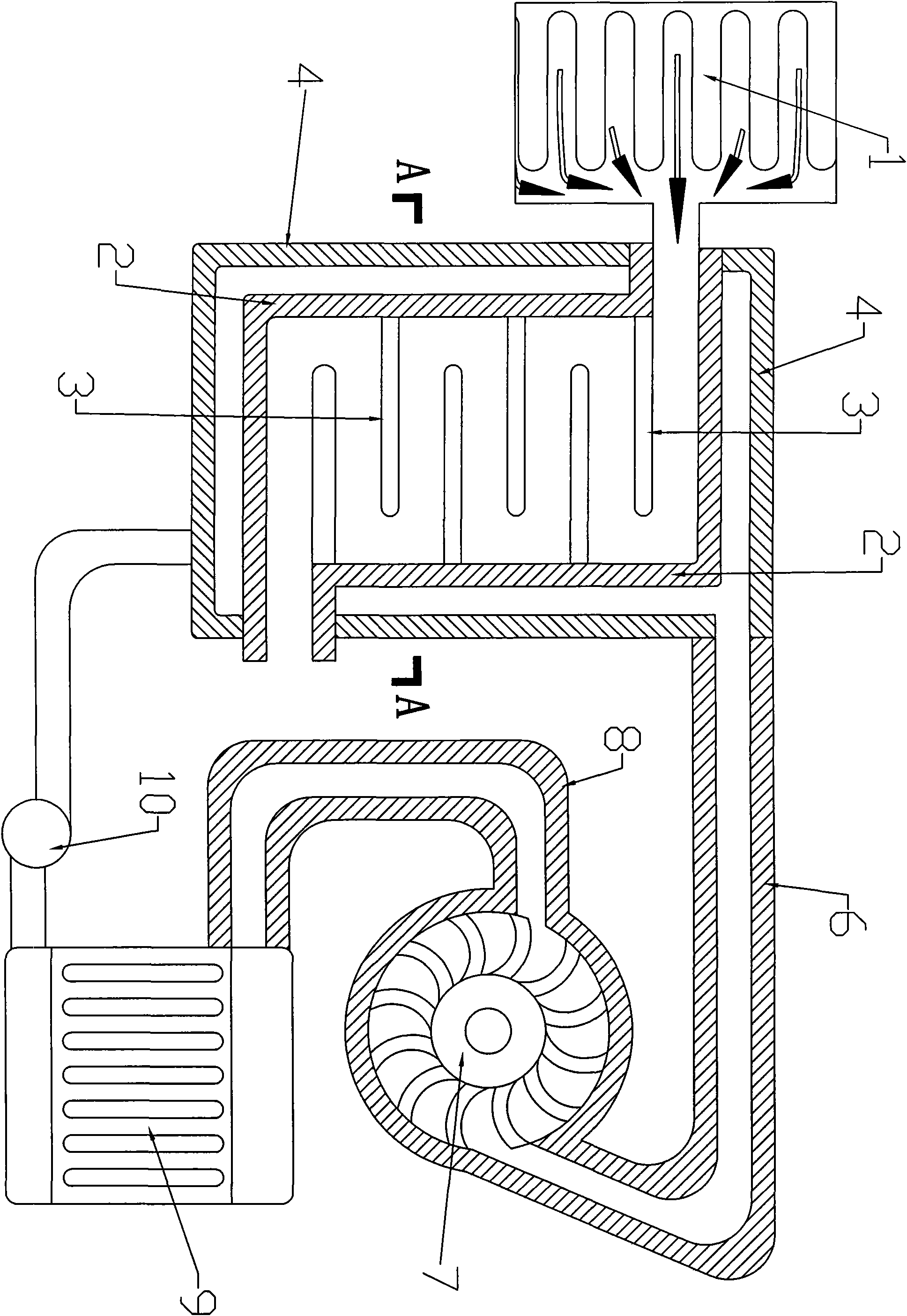
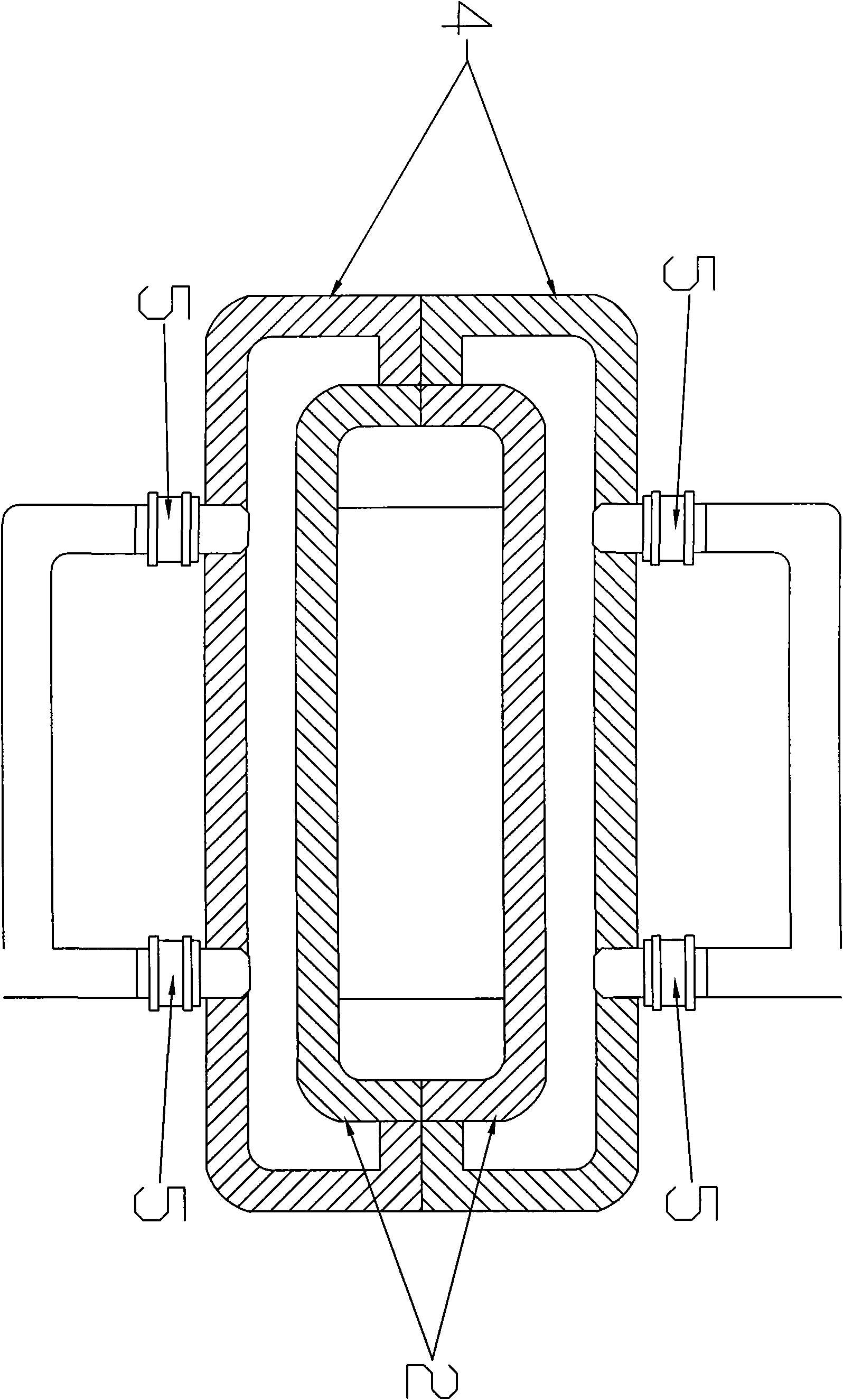
[0025] figure 1 The first embodiment shown is the heat source transverse counterflow type, which is composed of a spray nozzle 5, a rectangular hot wall 2, a steam turbine 7, a steam conduit 6, an exhaust pipe 8, a condensing radiator 9, a water pump 10, and a rectangular evaporator cover 4 Composed of transverse guide spacer 3. A plurality of transverse guide partitions are arranged inside the rectangular hot wall 2, and the rectangular hot wall 2 is covered with a rectangular evaporator cover 4, which forms an evaporation chamber. Several spray nozzles 5 are arranged around the rectangular evaporator cover 4, and the spray nozzles 5 extend into the evaporation chamber. The top of the evaporating device is the inlet of the heat source 1, and the bottom is the outlet of the heat source 1, a...


PUM


Abstract

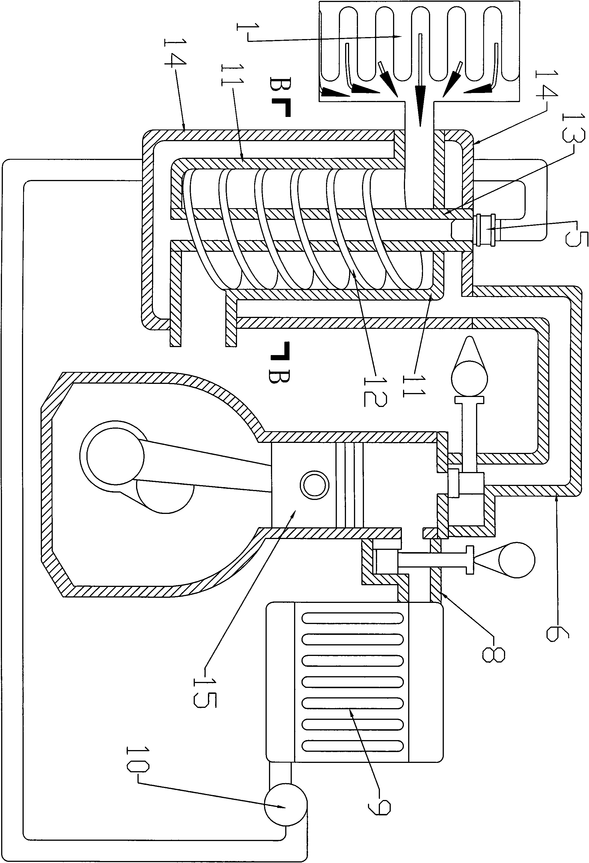
The invention relates to a high-speed evaporation and circulation steam engine for directly spraying liquid onto a hot wall. The steam engine mainly comprises a heat source, a rectangular hot wall, a transverse guide spacer, a rectangular evaporator cover, a spray nozzle, a steam turbine, a condensing radiator, a water pump, a tubular hot wall, a spiral guide spacer, a central heat pipe, a tubular evaporator cover, a piston-type sliding air valve steam engine, a planar hot wall, an evaporator cover, a piston-type air valve-free steam engine, an enclosing shell, a porous transverse spacer, a taper pipe hot wall, a Mu Dark rotary steam engine, a sealing steel shell, a straight round tube hot wall, a petal-shaped test tube hot wall, a tubular evaporator cover, a turbine steam engine and the like. The steam engine has the advantages of high heat efficiency, energy conservation, small size, small vibration, low noise, simple structure, mature technology and the like, and can be widely applied to automobiles, planes, ships, power generation, industrial and agricultural power and the like.

Description

technical field [0001] The present invention relates to a steam engine for directly spraying liquid onto a hot wall for a high-speed evaporation cycle. Background technique [0002] The existing boiler circulating steam engine has a large volume, low thermal efficiency and small application range. Contents of the invention [0003] The purpose of the present invention is to reduce the volume of the evaporator, improve thermal efficiency, save energy, increase reaction speed, and utilize various machines and industrial waste heat higher than 150°C. [0004] The principle is that after the liquid is sprayed into tiny water droplets, it will quickly evaporate into steam when it touches a hot wall whose temperature is higher than the boiling point. [0005] The present invention is achieved like this: the present invention has six technical proposals; [0006] The first embodiment is that the heat source transverse counterflow type is composed of a spray nozzle, a rectangula...

Claims


Application Information

Patent Timeline
IPC IPC(8): F01K11/00F01K11/02F01B17/04F01C1/18
Inventor 王鑫弘
Owner 王鑫弘
Learn More