Eureka AIR delivers breakthrough ideas for toughest innovation challenges, trusted by R&D personnel around the world.

Double effect device being capable of gas boosting, transferring and recycling

A gas pressurization and gas cylinder technology, which is applied in fluid pressure converters, gas/liquid distribution and storage, equipment loaded into pressure vessels, etc., can solve the problems of high price, gas sample or working medium pollution, gas outlet and inlet pressure The ratio is small and other problems, to achieve the effect of simple structure, low production cost, and avoiding loss

Inactive Publication Date: 2010-10-20
SHANGHAI JIAO TONG UNIV
View PDF4 Cites 11 Cited by
  • Summary
  • Abstract
  • Description
  • Claims
  • Application Information

AI Technical Summary

Problems solved by technology

There are a wide range of pressurization technologies and equipment available on the market, but they either easily cause a certain degree of pollution to gas samples or working fluids (such as oil-lubricated compressors), or have a large internal cavity scavenging volume that requires a large amount of gas to be compressed. Significance (such as air compressor), or the ratio of outlet air to inlet pressure is too small (such as diaphragm pump), in short, it cannot meet the technical characteristics requirements of high cleanliness, small volume and high pressure ratio
[0003] After searching the prior art, it is found that the Chinese patent "gas booster device" with publication number CN101566175 involves a gas booster that can achieve high pressure output , but the device achieves pressurization by compressing the oil chamber through the hydraulic oil pump, and the oil circuit system must not meet the requirements of the present invention for gas cleanliness, so it is generally used in low-demand industrial high-pressure gas supply
The Chinese patent "gas booster" with the publication number CN201149008 is mainly used in the pneumatic control path of the punch press, which can realize a boost of 0.7MPa to 2MPa. less precious rare gases
In addition, none of the previous schemes involved gas transfer and recovery functions
Literature research shows that there are ultra-high pressure clean helium pressurization systems for laser nuclear fusion ICF frozen targets and cold helium pressurization systems for Long March 3A rockets, etc., but such systems are huge in engineering and expensive, and are not included in the present invention. The fields of application involved

Method used


Image

  • Double effect device being capable of gas boosting, transferring and recycling
  • Double effect device being capable of gas boosting, transferring and recycling
  • Double effect device being capable of gas boosting, transferring and recycling

Examples


Embodiment 1

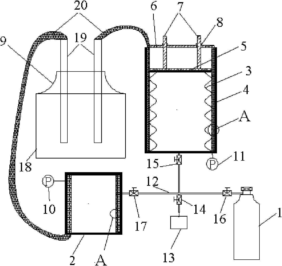
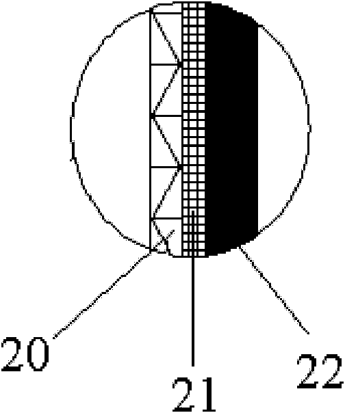
[0022] Such as figure 1 As shown, this embodiment includes: gas source gas cylinder 1, target gas cylinder 2, compressed gas cylinder 3, sleeve 4, flat plate 5, cover 6, adjusting rod 7, limiter 8, refrigerator 9, first Pressure gauge 10, second pressure gauge 11, pipeline 12, vacuum equipment 13, first valve 14, second valve 15, third valve 16 and fourth valve 17, wherein: the sleeve 4 is provided with a compressed gas cylinder 3. Both ends of the compressed gas cylinder 3 are sealed, one end of the compressed gas cylinder 3 is fixed on the bottom of the sleeve 4, and the other end is connected to the plate 5, the plate 5 is movable in the sleeve 4, and the cover 6 is fixed on the sleeve 4, the bottom end of the adjustment rod 7 is fixed on the flat plate 5, the top end of the adjustment rod 7 is socketed with the cover 6 and the top end is provided with a limiter 8, and the refrigerator 9 is connected with the target gas cylinder 2 and the sleeve 4 respectively. The target ...

Embodiment 2

[0037] In this embodiment: a low-temperature refrigerator in the liquid helium temperature zone (such as a commercial GM refrigerator with 1W at 4.2K) is used as a cold source, and its cold head is used to directly cool the compressed gas cylinder and the target gas cylinder.

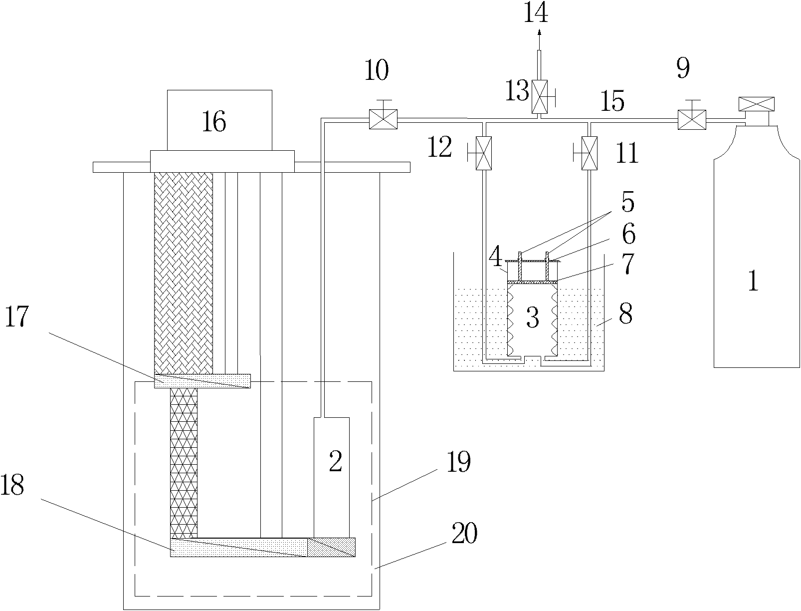
[0038] Such as image 3 As shown, this embodiment includes a source gas cylinder 1, a target gas cylinder 2, a compressed gas cylinder 3, a sleeve 4, an adjustment rod 5, a cover 6, a flat plate 7, a liquid nitrogen bath 8, a first valve 9, a second Valve 10, third valve 11 and fourth valve 12, fifth valve 13, vacuum equipment 14, pipeline 15, GM refrigerator 15, primary cold head 17, secondary cold head 18, low temperature screen 19, vacuum cover 20. Among them: the sleeve 4 is provided with a compressed gas cylinder 3, the two ends of the compressed gas cylinder 3 are sealed, one end of the compressed gas cylinder 3 is fixed on the bottom of the sleeve 4, the other end is connected with the plate 7, a...


PUM

PropertyMeasurementUnit
Diameteraaaaaaaaaa
Wall thicknessaaaaaaaaaa
The inside diameter ofaaaaaaaaaa

Abstract

The invention relates to a double effect device being capable of gas boosting, transferring and recycling, which belongs to the technical field of fluid machinery. The device comprises a source gas cylinder, a target gas cylinder, a compressed gas cylinder, a sleeve, a flat plate, a sealing gland, a regulating lever, a displacement restrictor, a refrigerator and a vacuum equipment, wherein the compressed gas cylinder is positioned in the sleeve, and both ends of the compressed gas cylinder are sealed; one end of the compressed gas cylinder is fixed with the bottom of the sleeve, and the otherend is connected with the flat plate; the flat plate is movably arranged in the sleeve; the sealing gland is fixed on the top of the sleeve; the bottom end of the regulating lever is fixed on the flat plate; the top end of the regulating lever is sleeved on the sealing gland, and the top ends o the the regulating lever and the sealing gland are respectively provided with the displacement restrictors; the refrigerator is respectively connected with the target gas cylinder and the sleeve; and the vacuum equipment, the compressed gas cylinder, the source gas cylinder and the target gas cylinder are communicated with each other through ducts. On the basis of the thermodynamic properties of compressible gases, the invention realizes the double effect being capable of boosting, transferring andrecycling for a small amount of special gases by the means of the background art combining cryogenic engineering and deformable metal structure.

Description

technical field [0001] The present invention relates to a device in the technical field of fluid machinery, in particular to a double-effect device for gas pressurization and transfer recovery Background technique [0002] In scientific experiments and industrial applications, it is often necessary to study the physical behavior characteristics of a small amount of special gas itself, or to require devices that use a certain gas as a working medium to operate under specified pressure conditions. In view of the preciousness, non-renewability, high cleanliness requirements, toxicity, corrosiveness and environmental pollution of this kind of gas, a reasonable mechanism must be used to realize the pressurization and recovery of the gas, and at the same time achieve cascade utilization and multiple purpose of repeated use. There are a wide range of pressurization technologies and equipment available on the market, but they either easily cause a certain degree of pollution to gas...

Claims


Application Information

Patent Timeline
IPC IPC(8): F15B3/00F17C5/06F17C7/00F17C13/04
Inventor 黄永华王晓建王如竹
Owner SHANGHAI JIAO TONG UNIV
Why Eureka
Eureka Blog
Learn More