Compound lathe and workpiece processing method

A processing method and lathe technology, applied in the field of compound lathes, can solve the problems of complex structure, high spindle position, and different processing of two difficult workpieces, and achieve the effect of reasonable configuration and improved support rigidity

Inactive Publication Date: 2014-03-12
NAKAMURATOME SEIMITSU IND
View PDF9 Cites 0 Cited by
  • Summary
  • Abstract
  • Description
  • Claims
  • Application Information

AI Technical Summary

Problems solved by technology

However, these lathes have the following problems: the shape of the bed is complicated and large, and the lower tool post arranged on the upper surface of the bed below the workpiece cutting position and the left and right guides for the right headstock (the lower Z-axis guide parts) and its feed screw to protect them from falling chips and cutting fluid, the structure of the cover becomes complicated, and in large lathes, the position of the spindle becomes higher
[0014] In addition, in the machining center of Patent Document 3, although there are two tool axes, there is only one mounting table for fixing the workpiece, so two workpieces cannot be machined in parallel.
For example, even if two workpieces are installed on the stage, it is difficult to process the two workpieces in parallel because the rotation of the stage around the upper and lower axes (the B axis of the machining center) changes the angles of the two workpieces at the same time. shape
In addition, turning a plurality of workpieces mounted on the stage cannot be performed by rotating the stage

Method used


Image

  • Compound lathe and workpiece processing method
  • Compound lathe and workpiece processing method
  • Compound lathe and workpiece processing method

Examples


Embodiment Construction

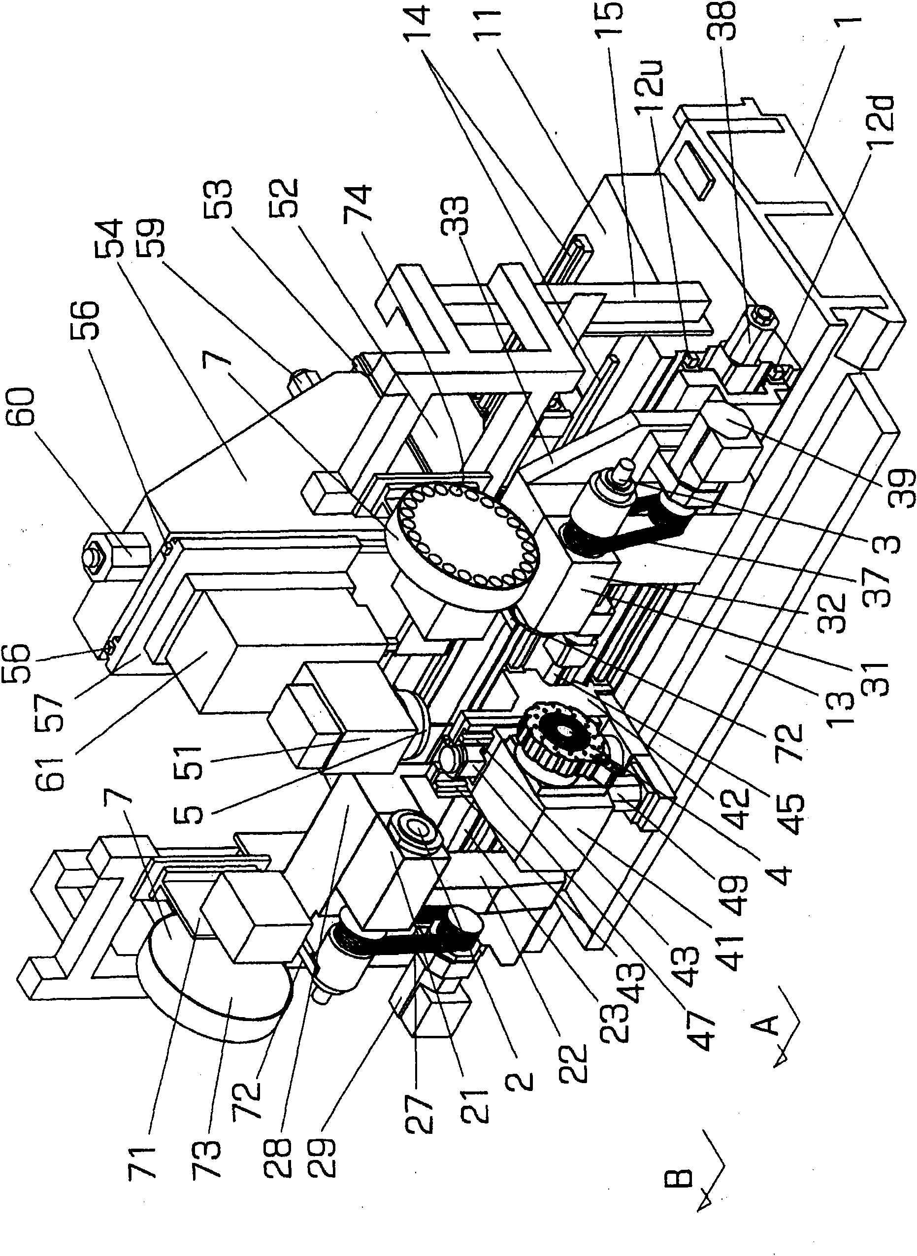
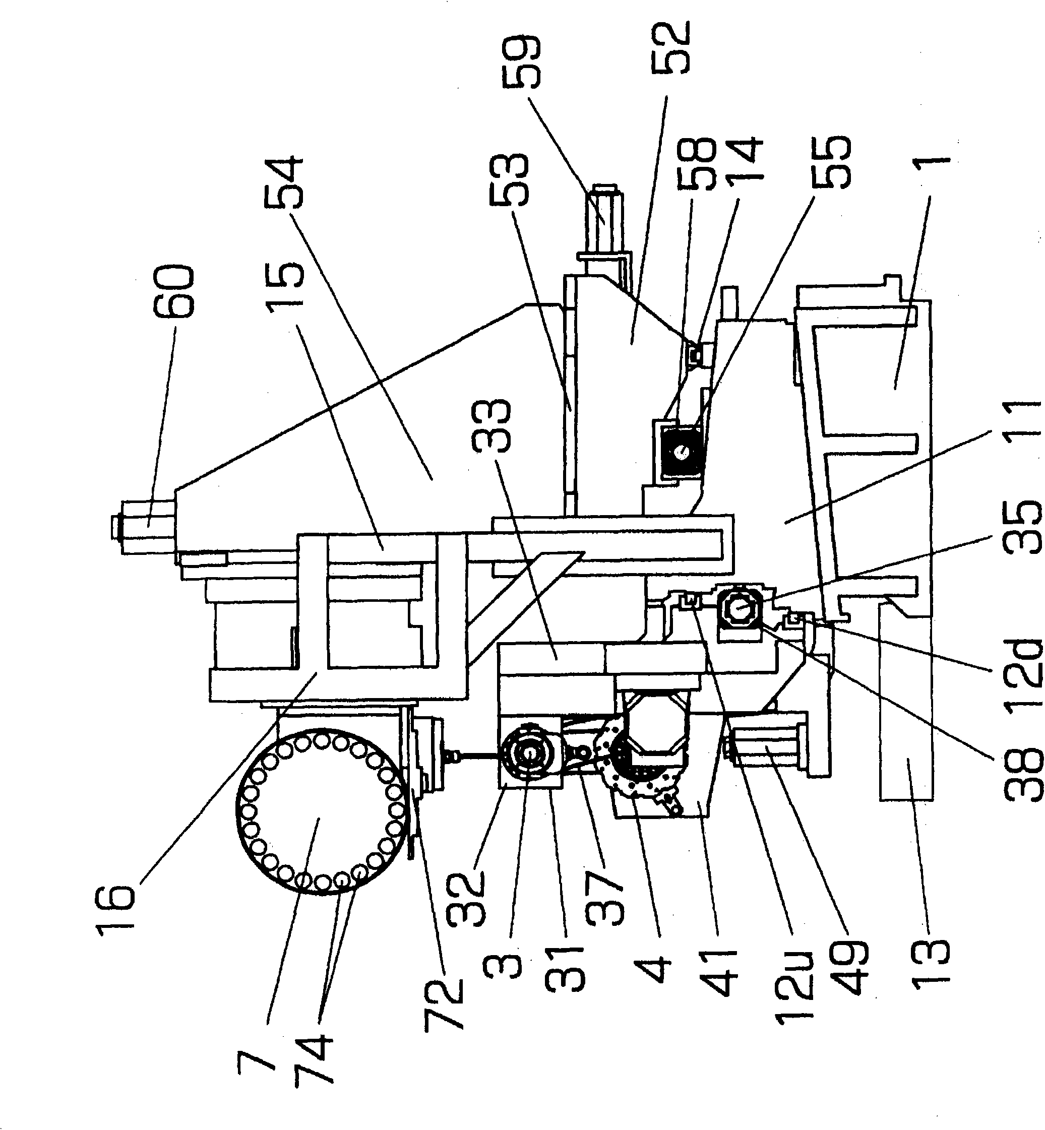
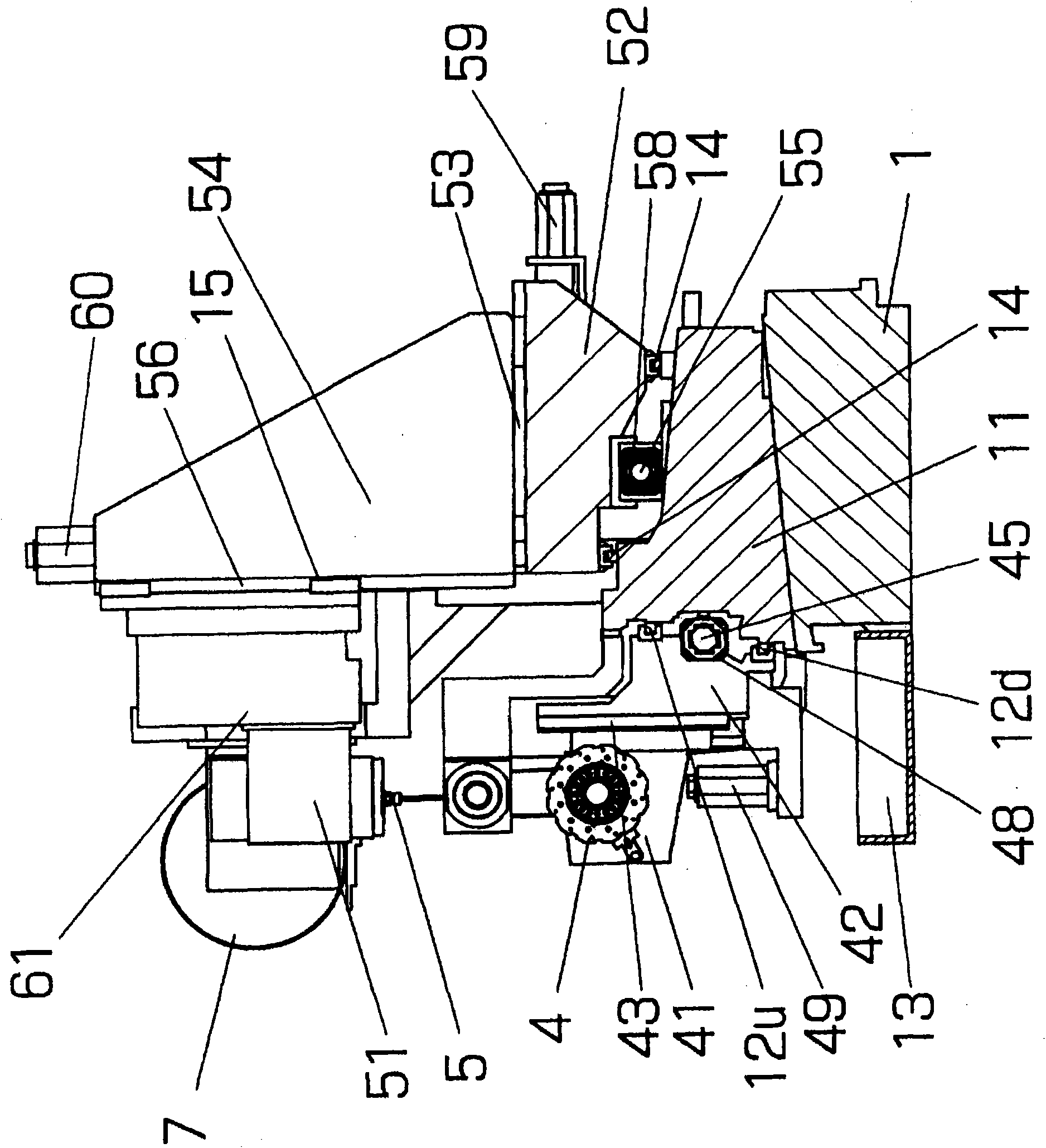
[0041] Next, specific examples of the present invention will be described with reference to the drawings. The accompanying drawing is a double-spindle opposed compound lathe with the structure of the present invention, which includes: two main shafts 2 and 3 facing each other on the same axis a; a tool shaft 5 arranged directly above the main shaft axis; and a tool shaft 5 arranged on the main shaft The tool turret 4 directly below the axis. The direction of the spindle axis a is the left-right direction when viewed from the operator side, the tool cutting direction of the tool shaft 5 and the tool turret 4 is the vertical direction, the direction orthogonal to these two directions is the front-rear direction, and the left and right are the Z-axis of the lathe , up and down is the X axis, front and rear is the Y axis, and the operator's side is the front.

[0042] Viewed from the operator's side, the left headstock 21 is fixed to the bed 11 , and the right headstock 31 can fr...


PUM


Abstract

The invention provides a compound lathe and a workpiece processing method. The compound lathe has the functions of a lathe and a processing center, so as to realize the lathe work, the large-plane processing and heavy cutting by using a large-size rotating tool and easily exchanging for two workpieces including the tool. The compound lathe is provided with a tool shaft (5), the moving position of which is controlled on three orthorhombic axial directions. The tool shaft (5) can rotate around a Y axis (on the front and back directions) relative to an operator and rotate around an axis parallel to a plane orthorhombic to the Y axis. Used as a workpiece holder, the tool shaft is provided with a structure as same as the traditional opposite double-spindle lathe, at least one turret (41) arranged under the spindle axis, and tool storages (7L, 7R) and tool exchanging devices (72L, 72R) above two spindles (2, 3) on two sides of the tool shaft (5).

Description

technical field [0001] The present invention relates to a compound lathe having the function of a machining center. Compared with the conventional compound lathe, the compound lathe of the present invention can use more kinds of rotary tools, and has greater processing capacity for plane processing, groove processing and hole drilling. In addition, the compound lathe of the present invention is capable of machining a surface inclined around axes in two orthogonal directions, which is impossible in a normal machining center. Background technique [0002] There is known a dual-spindle opposed compound lathe capable of performing surface machining, grooving, and hole machining on a workpiece by attaching a milling cutter or a drill to a tool shaft provided on a tool post. The dual-spindle opposed compound lathe proposed by the applicant of the present application in Patent Document 1 includes: the left main shaft, whose shaft is supported on the left headstock fixed to the bed...

Claims


Application Information

Patent Timeline
Patent Type & Authority Patents(China)
IPC IPC(8): B23B11/00B23Q3/155B23B25/00
CPCB23B3/16B23B3/30B23B25/00B23Q3/15534
Inventor 宮森千明石田拓也铃木孝作宫本高志
Owner NAKAMURATOME SEIMITSU IND
Why Eureka
Try Eureka