

Steam generator of annealing furnace and control method thereof
A technology for steam generators and annealing furnaces, applied in steam generation methods, steam generation, furnaces, etc., which can solve problems such as waste of electric energy and water waste
- Summary
- Abstract
- Description
- Claims
- Application Information
AI Technical Summary
Problems solved by technology
Method used
Image

Examples
Embodiment 1
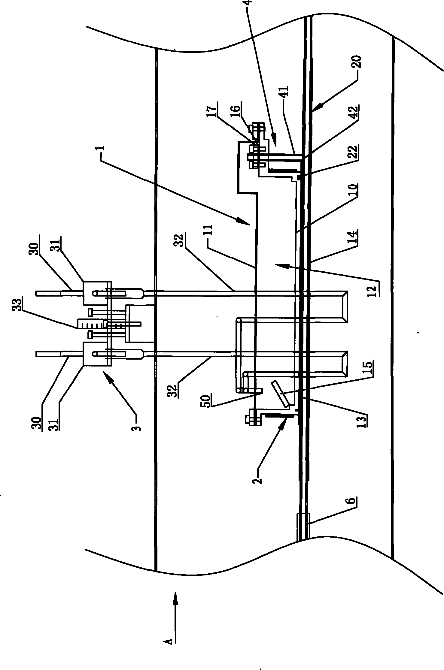
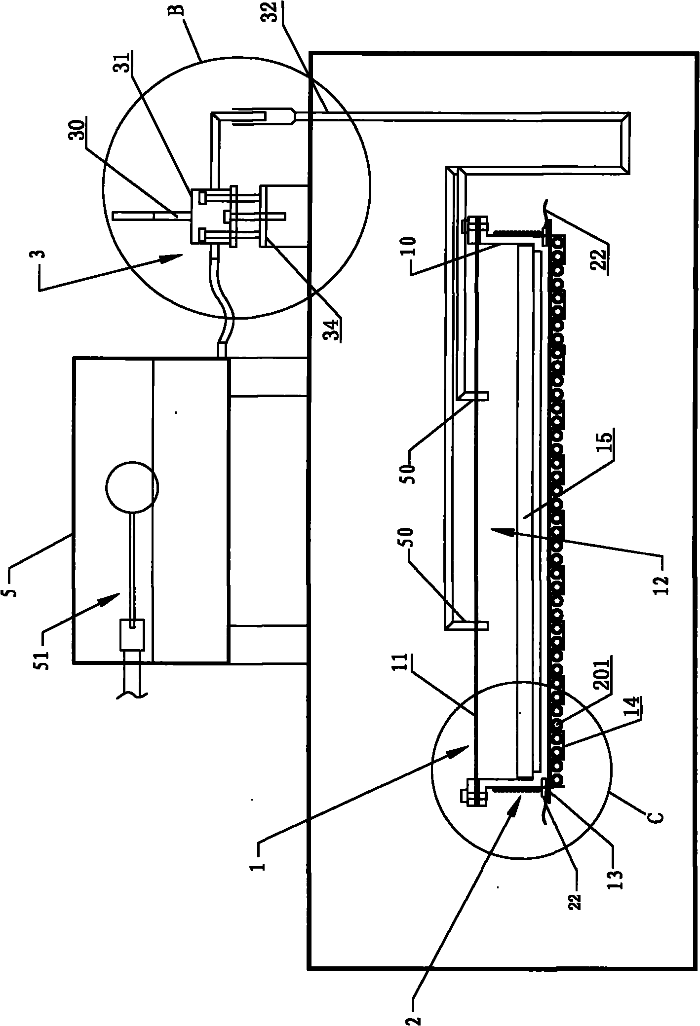
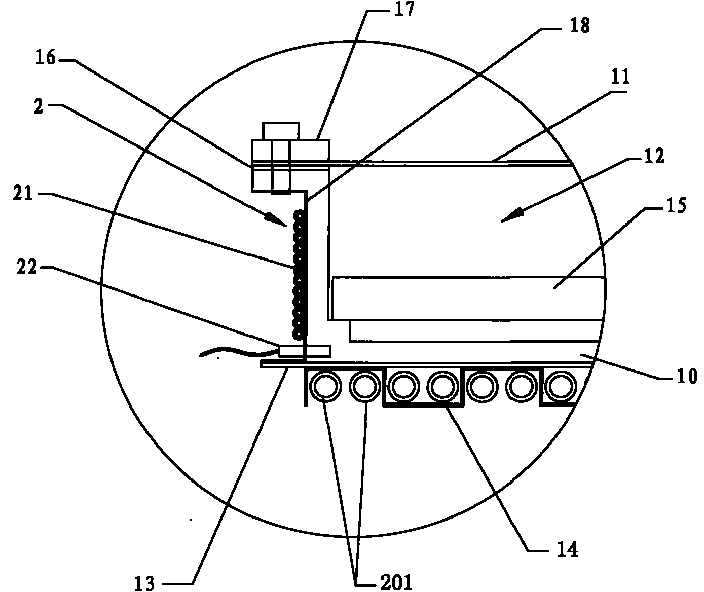
[0060] Such as Figure 1 to Figure 4Shown, a kind of annealing furnace steam generator, it comprises the electric heating device 2 that is provided with stranded resistance wire 21, built-in type dry burning liner 1, PLC controller, water adding device 3, thermocouple 22, and steam boiler A steam distributor 4 connected to the inner chamber; the built-in dry cooking liner 1 includes a dry cooking pot 10 and a stainless steel pot cover 11 covered on the top of the dry cooking pot 10, and the dry cooking pot 10 and the stainless steel pot cover 11 form a built-in dry cooking interior The inner tank cavity 12 of the tank 1, the bottom of the dry boiler 10 is provided with a heat conduction bottom plate 13, and the bottom of the heat conduction bottom plate 13 is provided with a heat conduction bending clamp 14 for wrapping the tube row 20 of the annealing furnace; the water adding device 3 includes a two-position three-way electromagnetic Valve 31, tubular measuring cup 30, and t...
Embodiment 2
[0089] Such as Figure 5 As shown, the difference from Embodiment 1 is that the steam generator for an annealing furnace described in Embodiment 2 has a steam introduction pipe 41 arranged on the side of the dry-fired pot 10 close to the high-temperature annealing zone 6, so that the dry-fired pot 10 is close to the high-temperature annealing zone 6, and this structure is suitable for the case where the cooling effect of the high-temperature wire is the main concern. The dry boiler 10 is arranged on the side near the exit of the annealing furnace in the high-temperature annealing zone 6 to generate steam by using the heat brought by the wire rod from the high-temperature zone, and to help the wire rod cool down. However, it is the inlet side of the annealing furnace that needs steam protection the most. When the steam source is located on the outlet side, the amount of steam has to be increased to ensure that the inlet is effectively protected. For most wire rods, more heat i...
Embodiment 3
[0091] Such as Figure 6 As shown, the difference from Embodiment 1 is that the annealing furnace steam generator described in Embodiment 3 is also located on the side of the built-in dry-burning liner 1 away from the high-temperature annealing zone 6 of the annealing furnace, and conducts heat. The corresponding position of the bent clamping plate 14 is provided with a heating device 7 in a phase change heat preservation zone. When this structure is used for annealing ferrous metal wires, it has a strong means to control the temperature of the phase change heat preservation zone. If the heat of the annealing furnace tube row 20 is insufficient, it can be heated to generate steam and keep the temperature of the dry boiler 10 slightly lower than the phase change temperature. If the heat preservation heating zone is set on the tube row behind the liner, it can better ensure that the temperature of the annealing furnace tube 201 wrapped by the heat-conducting bending clamp 14 is ...
PUM
 Abstract
Description
Claims
Application Information