
Passive optical network system and its operation method

一种光通信系统、光纤网的技术,应用在光多路复用系统、传输系统、数字传输系统等方向,能够解决分配量减少、品质影响、分配处理复杂等问题,达到抑制上行频带分配量的减少、提高频带利用效率的效果

Inactive Publication Date: 2010-10-27
HITACHI LTD
View PDF3 Cites 8 Cited by
  • Summary
  • Abstract
  • Description
  • Claims
  • Application Information

AI Technical Summary

Problems solved by technology

That is, the communication interruption (standby) time in the ONU in operation increases, which affects the quality of the signal requiring real-time performance, or the allocation process of the communication capacity (frequency band) to all ONUs by DBA becomes complicated, and the allocation amount decreases

Method used


Image

  • Passive optical network system and its operation method
  • Passive optical network system and its operation method
  • Passive optical network system and its operation method

Examples


Embodiment Construction

[0036] Hereinafter, the configuration and operation of the PON system of the present invention will be described by taking the configuration and operation of the GPON specified in ITU-T Recommendation G984.3 as an example using the drawings.

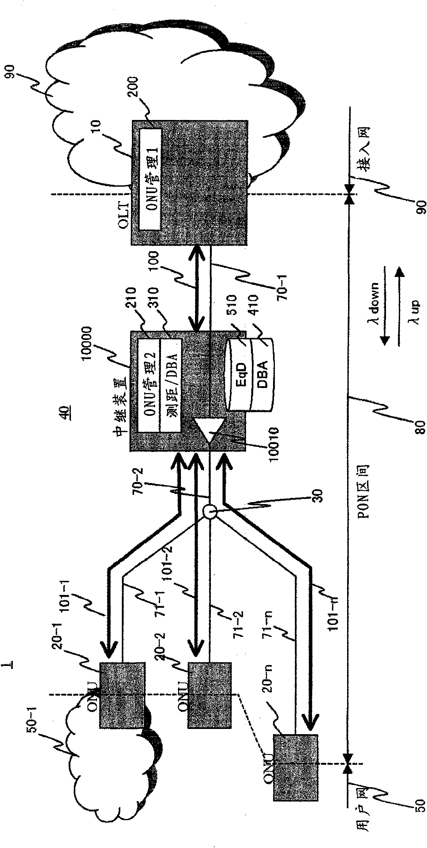
[0037] figure 1 It is a network configuration diagram showing a configuration example of an optical access network using a PON according to the present invention, and shows a configuration example in a case where REs are inserted into a PON converging optical fiber.

[0038] The optical access network 1 is a network composed of a central office device (OLT) 10, a plurality of user devices (ONU) 20-1-20-n, an optical splitter 30, an Branch optical fiber 71-1~71-n, in the PON40 constituted by the signal relay device (RE) 10000 inserted between 70-1 and 70-2 in the middle of the line optical fiber 70, each ONU20 (20-1~20 -n) Each is connected to a user network (or a terminal such as a PC or a telephone; only the user network 50-1 is shown ...


PUM


Abstract

In the configuration of an optical communication system interconnecting a parent station and a plurality of child stations via an optical fiber network equipped with an optical splitter, RE is provided having a measuring unit for measuring a transmission distance or time to a child station, a determining unit for determining a timing when a child station transmits a signal, in accordance with a transmission bandwidth request from the child station, and a signal processing unit for processing a signal received from a child station and transmitting the processed signal to the parent station. When a burst signal is received from each child station at the determined timing, a portion of the header of the burst signal is deleted, and a dummy signal is inserted into the deleted area and a gap area between received burst signals to convert the burst signals into a series of signals to be sent to the parent station.

Description

technical field [0001] The present invention relates to the structure and operating method of an optical passive network system in which multiple user devices share an optical transmission line, and in particular to the structure and operating method of a system suitable for system expansion such as extending transmission distance or increasing accommodated user devices. Background technique [0002] The demand for communication using broadband has increased, and the access line used by users has shifted to a large-capacity access line using optical fiber instead of technology using telephone lines such as DSL (Digital Subscriber Line). At present, from the perspective of line laying and maintenance management costs, PON (Passive Optical Network) system (hereinafter referred to as PON, or optical passive network system, or sometimes called passive optical network) is widely used as an access network. system). The PON uses optical fibers and optical splitters from the centra...

Claims


Application Information

Patent Timeline
Patent Type & Authority Applications(China)
IPC IPC(8): H04B10/17H04Q11/00H04L1/00H04B17/40H04L12/44
CPCH04B10/272H04J3/0682H04Q11/0067H04J14/0252H04Q2011/0079H04Q2011/009H04J14/0247H04J3/1694
Inventor 水谷昌彦矢岛佑辅土屋明彦
Owner HITACHI LTD
Learn More