Horizontal shaft micro-mechanical tuning fork gyroscope adopting electrostatic balance comb tooth driver

A tuning fork gyro and driver technology, which is applied in the direction of gyro effect for speed measurement, gyroscope/steering sensing equipment, instruments, etc., can solve the problems of affecting gyro performance, increasing device cost, and detecting modal damping, so as to improve sensitivity and resolution, reduce electromechanical coupling, and improve linearity

Inactive Publication Date: 2010-11-03
PEKING UNIV
View PDF0 Cites 21 Cited by
  • Summary
  • Abstract
  • Description
  • Claims
  • Application Information

AI Technical Summary

Problems solved by technology

[0004] At the same time, the existing capacitive micromachined tuning fork gyro uses a variable gap detection capacitor, and the detection mode is greatly affected by the damping of the pressure film, which often requires vacuum packaging, which increases the cost of the device
Moreover, in order to realize the high-performance horizontal-axis micro-mechanical tuning fork gyroscope working under normal pressure, its structural layout is not optimized enough. Moreover, due to processing errors and other reasons, the coupling from the detection mode to the driving mode cannot be completely coupled during operation. suppressed, this residual coupling also affects gyro performance

Method used


Image

  • Horizontal shaft micro-mechanical tuning fork gyroscope adopting electrostatic balance comb tooth driver
  • Horizontal shaft micro-mechanical tuning fork gyroscope adopting electrostatic balance comb tooth driver
  • Horizontal shaft micro-mechanical tuning fork gyroscope adopting electrostatic balance comb tooth driver

Examples


Embodiment Construction

[0017] The present invention will be described in detail below in conjunction with the accompanying drawings and embodiments.

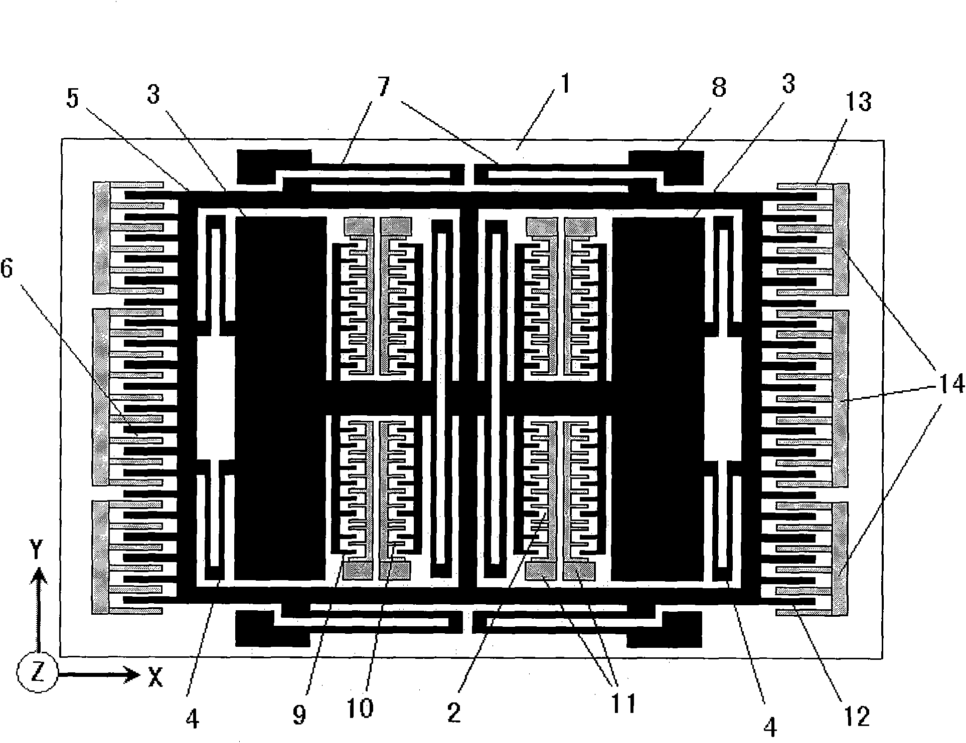
[0018] like figure 1 As shown, the present invention is a Y-axis micromachined tuning fork gyroscope, which includes a substrate 1, more than one set of drive capacitors 2, two detection masses 3, a drive folded beam 4, a frame 5, and more than one set of detection capacitors 6, Detect folded beam 7 and anchor point 8. One side of each group of drive capacitors 2 is connected to the respective adjacent proof mass 3, and each proof mass 3 is fixedly connected to the frame 5 by driving the folding beam 4, and the frame 5 is respectively connected to the detection capacitor 6 and the detection folding beam 7 to detect folding The beam 7 is fixedly connected to the anchor point 8, and the anchor point 8 is fixed on the substrate 1; the other side of each group of driving capacitors 2 is sequentially connected to the detection folded beam 7 by driving the...


PUM


Abstract

The invention relates to a horizontal shaft micro-mechanical tuning fork gyroscope adopting an electrostatic balance comb tooth driver, which comprises a substrate, more than one group of driving capacitors, two detection mass blocks, a driving folded beam, a frame, more than one group of detection capacitors, a detection folded beam and an anchor point, wherein one side of each group of driving capacitors is connected with the adjacent detection mass block, the detection mass blocks are fixedly connected with the frame through the driving folded beam, the frame is respectively connected with the detection capacitors and the detection folded beam, and the detection folded beam is connected with the anchor point fixed on the substrate; and the other sides of each group of driving capacitors are sequentially connected to the detection folded beam through the driving folded beam and the frame, and the detection folded beam is connected with the anchor point fixed on the substrate. Because adopted driving movable comb teeth and adopted driving fixed comb teeth have the same thickness along the Z-axis direction, have different positions and are symmetrically distributed, the invention realizes the purpose of effectively inhibiting the coupling from a detection mode to a driving mode, thereby improving the sensitivity and the resolution of the gyroscope. The invention can be widely applied to detection of rotational angular speed of objects in various fields.

Description

technical field [0001] The invention relates to a micromechanical gyroscope, in particular to a horizontal axis micromechanical tuning fork gyroscope using an electrostatic balance comb driver. Background technique [0002] Micromachined gyroscopes are gyroscopes with characteristic dimensions in the order of microns processed by micromachining technology. They are small in size, light in weight, low in cost, low in power consumption, and easy to integrate. Therefore, they have extensive and urgent market demands, and strong market drivers have greatly promoted The rapid development of micro-mechanical gyroscopes has been successfully used in civil applications such as automobiles and consumer electronics, as well as military applications such as spacecraft and tactical missiles. With the expansion of application fields and the improvement of use requirements, monolithic integration of multi-sensitive axis inertial sensors and micro-inertial measurement units has been put on...

Claims


Application Information

Patent Timeline
Patent Type & Authority Applications(China)
IPC IPC(8): G01C19/56G01C19/5621
Inventor 郭中洋杨振川赵前程林龙涛刘雪松丁海涛崔健闫桂珍
Owner PEKING UNIV
Why Eureka
Try Eureka