Micron-nano scale in-situ nano indentation and scratching test system

A nano-indentation and testing system technology, which is applied in the direction of testing material hardness, measuring devices, instruments, etc., can solve the problems of loading force model error, high price, and inability to detect loading force, etc.

Inactive Publication Date: 2010-11-03
赵宏伟
View PDF3 Cites 48 Cited by
  • Summary
  • Abstract
  • Description
  • Claims
  • Application Information

AI Technical Summary

Problems solved by technology

[0011] However, the above-mentioned test devices have shortcomings: the devices developed by M.A.Wall of LLNL and LBNL cannot test the mechanical parameters of materials because they cannot detect the loading force, and cannot study the influence of load on material deformation and damage; the devices of A.M.Minor and others have passed The relationship between the voltage applied to the piezoelectric element and its deformation is converted to obtain the loading force, resulting in complex testing and too many offline operations. There are also model errors and parameter errors in the conversion of loading force, which affects the reliability of the test results in terms of value. Reliability; there are special-purpose limitations in test devices based on MEMS technology
At present, the in-situ nanomechanical testing instruments of commercial products are only produced by the American Hysitron Company, which is very expensive and is also embargoed to my country; other in-situ nanomechanical testing has certain shortcomings or is limited by special purposes

Method used


Image

  • Micron-nano scale in-situ nano indentation and scratching test system
  • Micron-nano scale in-situ nano indentation and scratching test system
  • Micron-nano scale in-situ nano indentation and scratching test system

Examples


Embodiment Construction

[0029] The details of the present invention and its specific implementation will be further described below in conjunction with the embodiments shown in the accompanying drawings.

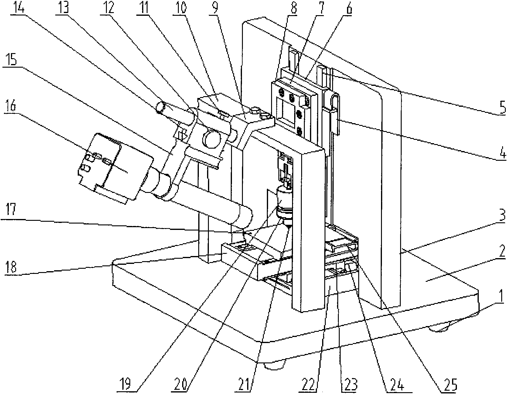
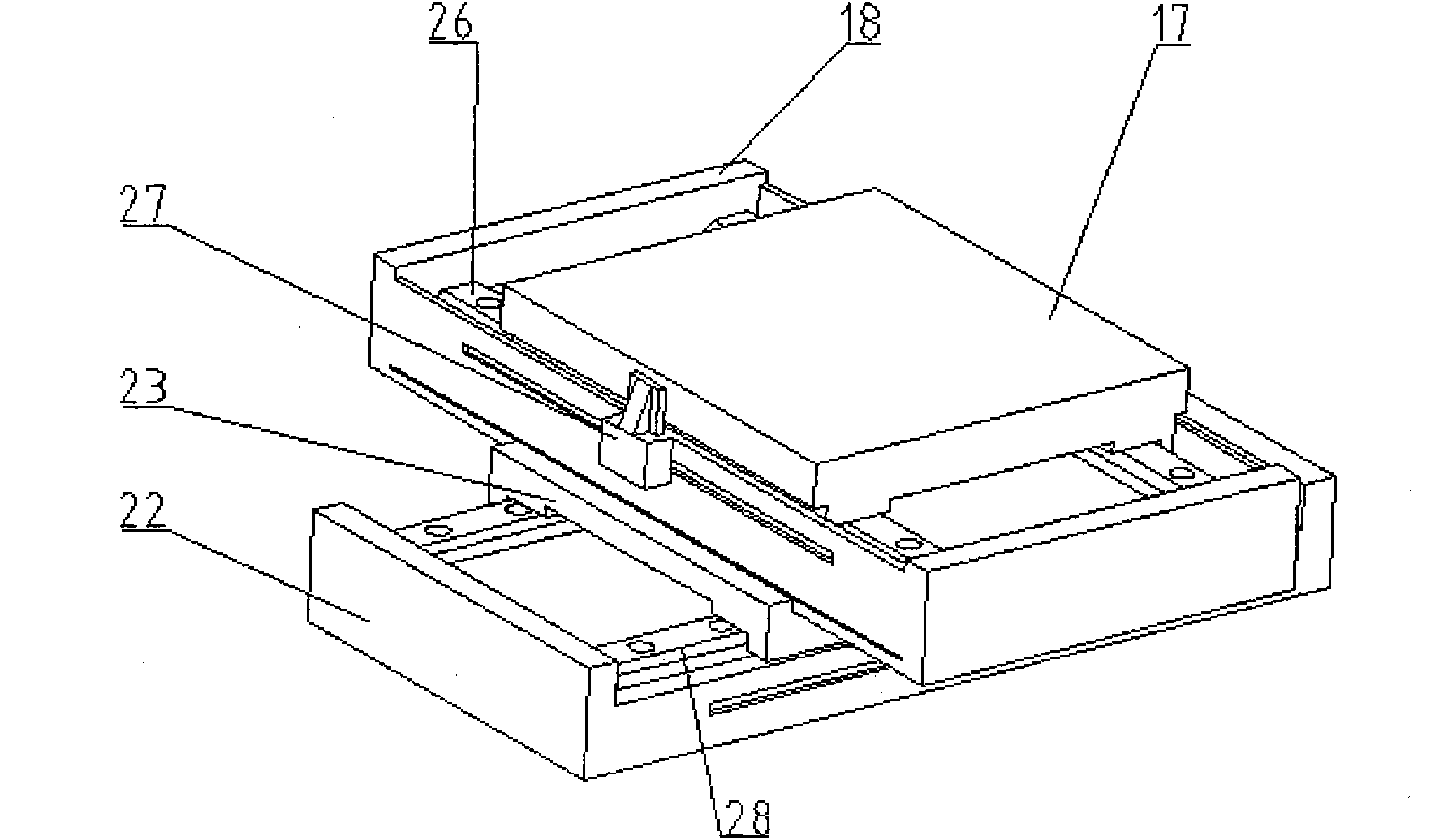
[0030] A micro-nano-level in-situ nano-indentation scoring test technology and system, mainly composed of a precision positioning platform 17 in the X and Y axis directions, a precision linear positioning platform 6 in the Z axis direction, a precision press-in drive unit, a load signal detection unit, It consists of a displacement signal detection unit and a high-resolution digital microscopic imaging system for observing material deformation and damage during storage testing. The precise positioning platform 17 in the X and Y axis directions is assembled on the base 2, and the precise linear positioning platform 6 in the Z axis direction is installed on the side plate 3, and the drive unit is precisely pressed in to detect the precision of the pressure of the diamond tool head pressed into the mat...


PUM


Abstract

The invention relates to a micron-nano scale in-situ nano indentation and scratching test system which integrates driving, precise loading and signal detection, micron-nano scale mechanics performance testing, ultraprecise scratching processing and high resolution in-situ observing as one. The system is mainly composed of a precise positioning platform at X-axis and Y-axis directions, a precise linear positioning platform at Z-axis direction, a precise indentation driving unit, a load signal and displacement signal detection unit and a high resolution digital microscopic imaging system for observing and storing material deformation and damage conditions in the test process. The precise positioning platform at the X-axis and Y-axis directions is assembled on a base, the precise linear positioning platform at the Z-axis direction is assembled on a side plate, the precise indentation driving unit, a precise mechanical sensor for detecting the indentation material pressure of a diamond tool head and a precise displacement sensor for detecting the indentation depth of the diamond tool head to along the Z-axis direction are assembled on the precise linear positioning platform at the Z-axis direction, and the high resolution digital microscopic imaging system is assembled on a beam.

Description

technical field [0001] The invention relates to a precision automatic test and test system integrating drive, precise loading and detection, micro-nano level mechanical property test, ultra-precise scribing processing and in-situ observation, especially for the micro-mechanical property test of various specimens or materials The devices for nano-indentation / scratch experiment, in-situ nano-indentation / scratch experiment and micro-nano-scale in-situ diamond scribing processing belong to the precision testing equipment of optomechanical integration. Precision instruments are an important guarantee for promoting scientific and technological progress and social development. This invention is a special testing instrument for measuring the micromechanical performance parameters of various test pieces or materials. It can test and evaluate the mechanical properties and service behavior of precision components. The design and manufacturing process optimizes the process, improves its pe...

Claims


Application Information

Patent Timeline
Patent Type & Authority Applications(China)
IPC IPC(8): G01N3/00G01N3/46G01B11/16
Inventor 赵宏伟黄虎曲兴田曲涵隋航
Owner 赵宏伟
Why Eureka
Try Eureka