Device and method for testing thermo-mechanical fatigue

A thermomechanical fatigue and heating device technology, applied in the direction of applying repetitive force/pulsation force to test the strength of materials, etc., can solve the problems of complex equipment, long heating and cooling cycles, and high energy consumption

Inactive Publication Date: 2010-11-03
INST OF MECHANICS - CHINESE ACAD OF SCI
View PDF0 Cites 18 Cited by
  • Summary
  • Abstract
  • Description
  • Claims
  • Application Information

AI Technical Summary

Problems solved by technology

[0003] The technical problem to be solved by the present invention is to overcome the limitations of complex equipment, high energy consumption, and long heating and cooling cycle in the prior art, thereby providing a simple structure, low energy consumption, rapid heating and cooling, capable of high-cycle or ultra-high Thermomechanical fatigue test device for cycle fatigue test, and method for fatigue test using the device

Method used


Image

  • Device and method for testing thermo-mechanical fatigue
  • Device and method for testing thermo-mechanical fatigue
  • Device and method for testing thermo-mechanical fatigue

Examples


Embodiment 1

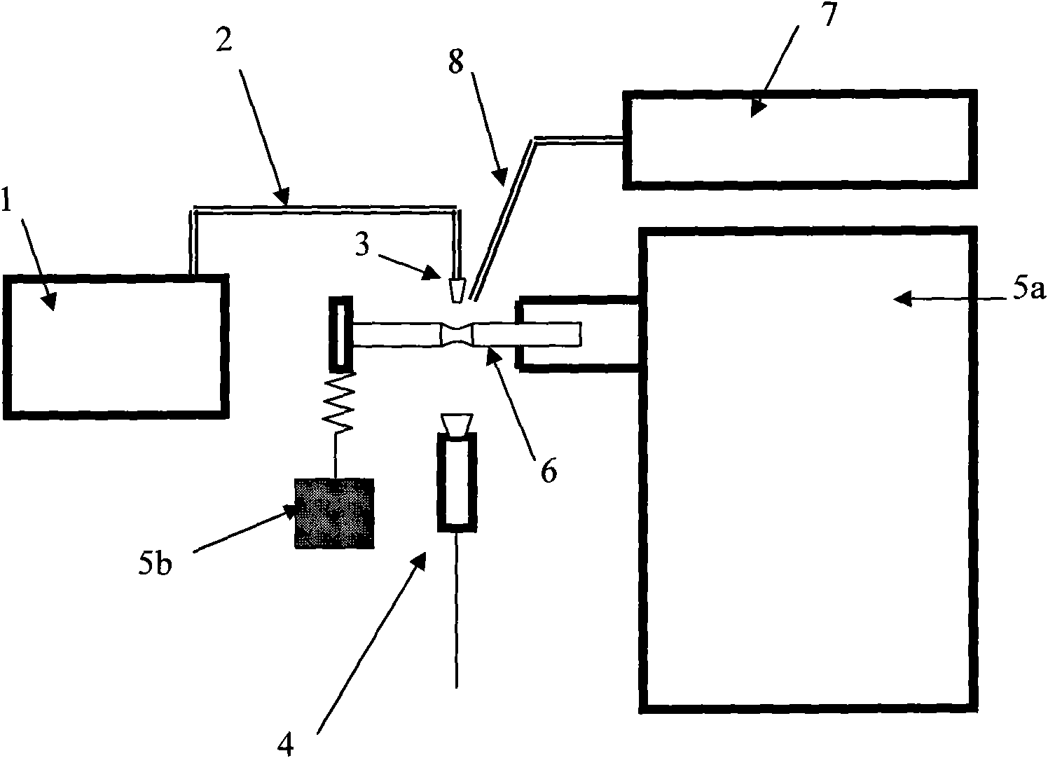
[0033] like figure 1 In the device shown, the loading device is a weight 5b; the sample 6 is set on the rotating shaft of the main body 5a of the rotating bending fatigue machine, and the other end of the sample is mechanically loaded by the weight 5b. The heating device includes a laser light source 1, a focusing lens 2, and may also include a heating device (not shown in the figure) for heating the entire experimental sample. The laser light emitted by the continuous laser light source 1 is transmitted through the optical fiber 2, and then focused on the surface of the sample 6 by the focusing lens 3 to heat the surface of the sample 6. When the overall heating of the test sample is required, the overall heating device can be started to heat the sample. heating. The temperature measuring device is an infrared temperature measuring device, and other temperature measuring devices capable of accurately measuring temperature may also be used. The temperature of the sample heat...

Embodiment 2

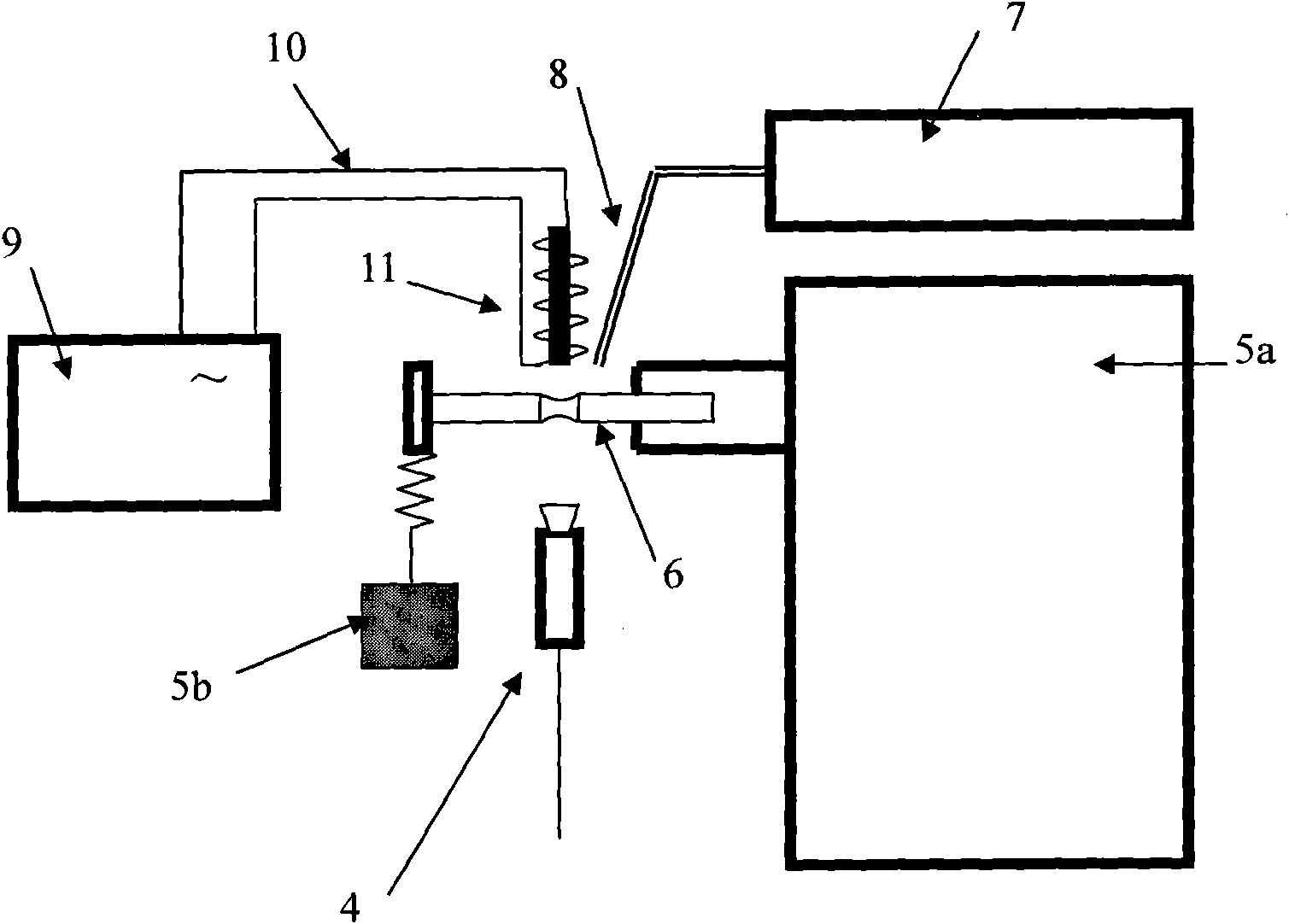
[0046] like image 3In the device shown in , the sample 6 is set on the rotating shaft of the main body 5a of the rotating bending fatigue machine, and the other end of the sample is mechanically loaded by the weight 5b. In the present embodiment, the heating device is: an AC power supply and an induction coil; the AC power supply 9 is connected to the induction coil 11 through a wire 10, and the induction coil 11 generates a high-frequency electromagnetic field to excite an induced current on the surface / subsurface of the sample 6, thus affecting the surface of the sample. for heating. The temperature of the sample heating point is measured by an infrared temperature measuring device 4 . The ambient gas stored in the gas source 7 is sprayed onto the surface of the sample through the gas nozzle 8 to control the ambient atmosphere of the thermomechanical fatigue process.

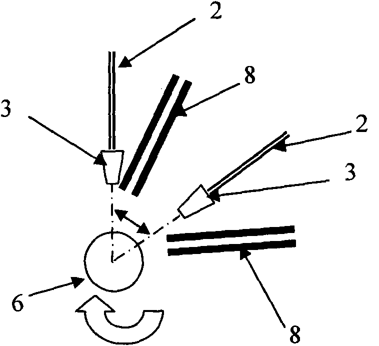
[0047] like Figure 4 As shown, the induction coil 11 and the gas nozzle 8 can be arranged from differe...


PUM


Abstract

The invention relates to a device and a method for testing thermo-mechanical fatigue. The device comprises a rotary bending fatigue loading device, a heating device for applying a temperature load to a fatigue sample, a sample surface gaseous environment control device and a temperature measurement device. Through the device and the method in combination with the conventional device and the conventional method for rotary bending fatigue and high-speed heating, the temperature load effect of different phase differences on the sample is ensured under the condition of rotary bending fatigue loading. The mechanical load of the fatigue sample is applied and controlled by the rotary bending loading device, while the temperature load is applied and controlled by the heating device and the temperature measurement device; and the phase difference of a temperature waveform and a mechanical load waveform is controlled by the number and the positions of the heating ends of the heating device. The thermo-mechanical fatigue testing device of the invention has the advantages of simple structure, low energy consumption and the capability of realizing rapid temperature rise and drop and accurate phase difference control between the mechanical load waveform and the temperature waveform.

Description

technical field [0001] The invention relates to a device and a method for performing thermomechanical fatigue experiments on material samples. Background technique [0002] Thermomechanical fatigue refers to the fatigue behavior under the condition of simultaneous mechanical load cycle and temperature cycle, usually the mechanical cycle load and temperature cycle have different phases. The existing thermomechanical fatigue test equipment is basically realized by the axial and axial torsion two-way hydraulic servo fatigue testing machine combined with heating and cooling devices. Although the mechanical frequency of the hydraulic servo fatigue testing machine can reach 100Hz, for the temperature cycle, due to the overall heating of the sample, the cooling mainly depends on the gas forced convection cooling, and the cooling rate is low. Therefore, the temperature cycle frequency of the experiment process is determined to be low. At present, the frequency of this kind of ther...

Claims


Application Information

Patent Timeline
Patent Type & Authority Applications(China)
IPC IPC(8): G01N3/34
Inventor 谢季佳赵爱国武晓东洪友士
Owner INST OF MECHANICS - CHINESE ACAD OF SCI
Why Eureka
Try Eureka