Intelligent temperature control method for array light receiving/transmitting module in optical switch

An optical transceiver module and optical switch technology, applied in the field of optical communication, can solve the problems of inability to completely eliminate measurement errors, poor expansion of temperature control at more points, and low accuracy.

Inactive Publication Date: 2010-11-03
UNIV OF ELECTRONICS SCI & TECH OF CHINA
View PDF6 Cites 11 Cited by
  • Summary
  • Abstract
  • Description
  • Claims
  • Application Information

AI Technical Summary

Problems solved by technology

At present, to solve the measurement error of the analog temperature sensor, the compensation circuit is generally used, but the implementation cost is high, and the compensation circuit cannot completely eliminate the measurement error caused by the device process, etc.
[0010] Third, the temperature measuring element adopts a digital temperature sensor, and its accuracy can be guaranteed to a certain extent, but since the highest precision of the digital temperature sensor is 12 bits, that is, the temperature signal can be converted into a 12-bit binary digital signal at most, its inherent characteristics More accurate temperature measurement data cannot be obtained, and the cost of applying it to a multi-point control system is relatively high
[0011] Fourth, the current various temperature control systems have a relatively narrow temperature control range, the maximum range is -40~100°C, which cannot meet the application of some special circumstances, such as the temperature range is -55~120°C, and the accuracy is not good. high
[0012] Fifth, the current various temperature control systems are basically single-point control, which is difficult to apply to multi-point temperature control systems, and the temperature control scalability for more points is poor

Method used


Image

  • Intelligent temperature control method for array light receiving/transmitting module in optical switch
  • Intelligent temperature control method for array light receiving/transmitting module in optical switch
  • Intelligent temperature control method for array light receiving/transmitting module in optical switch

Examples


Embodiment Construction

[0045] In the following, the temperature control system of the array optical transceiver module applied to the optical switch of the present invention will be further described in detail in conjunction with the specific embodiments.

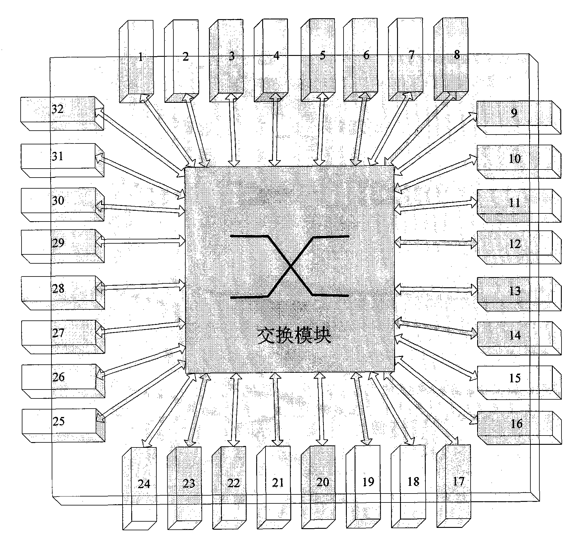
[0046] figure 1 It is a schematic diagram of a 32-port optical switch. figure 1 The numbers 1 to 32 in the optical switch represent the 32 optical transceiver modules in the optical switch. The working mode is as follows: the optical signal is first input to the optical transceiver module at the input end, and the optical signal is converted into an electrical signal by the optical receiver in the module. Then complete the signal exchange through the configured switch, and switch to an optical transceiver module at the output end, and complete the electro-optical conversion and output through the optical transmitter in the output module to realize the exchange of optical information in the optical switch. For example, when the first optical signa...


PUM


Abstract

The invention discloses an intelligent temperature control method for an array light receiving/transmitting module in an optical switch. The scheme comprises a temperature sensor, a voltage amplifying circuit, an 8-channel 16-bit D/A (digital/analogue) conversion module, an 8-channel 16-bit A/D conversion module, a central processing module, an FPGA (field programmable gate array) configuration module, a semiconductor refrigerator TEC, a keyboard, a liquid crystal display screen, a serial communication module and the like. The temperature sensor bonded with the array light receiving/transmitting module converts a temperature signal into a voltage signal which is amplified and then processed by the A/D conversion module and transmitted to the central processing module; the central processing module calculates a control quantity by using a temperature control algorithm, and the control information is converted into a control quantity of the TEC by the D/A conversion module; and the TEC realizes multi-point intelligent temperature control. The invention can implement temperature control on multiple modules at the same time in a large range and has the characteristics of real-time performance, high precision, high efficiency, large temperature control range, high extensibility and the like.

Description

Technical field [0001] The invention belongs to the field of optical communication technology, and specifically relates to a high-precision temperature detection and control technology for an array optical transceiver module of an optical switch. Background technique [0002] The optical switch is the information processing hub of the entire optical communication system, and is one of the important devices that are indispensable and widely used in the future optical communication field. In engineering applications, the temperature characteristics of the optical transceiver module in the optical switch is a key factor that affects the accuracy and stability of the optical signal reception and transmission of the optical switch. To enable the optical switch to work normally and stably under any harsh temperature environment, it is necessary to perform high-precision and fast-response temperature control on the optical transceiver module in the optical switch. [0003] At present, th...

Claims


Application Information

Patent Timeline
Patent Type & Authority Applications(China)
IPC IPC(8): G05D23/19H04Q11/00
Inventor 张崇富付纳科邱昆
Owner UNIV OF ELECTRONICS SCI & TECH OF CHINA
Why Eureka
Try Eureka