
Power converter and input/output frequency conversion method

A power converter and output frequency technology, which is applied to conversion equipment for intermediate conversion to DC conversion, conversion equipment that can be converted to DC without intermediate conversion, and output power conversion devices, etc., can solve the conversion efficiency loss, cost High, it is difficult to apply to various loads and various output frequency requirements, etc., to achieve the effect of improving conversion efficiency and reducing volume

Active Publication Date: 2013-03-13
SIEMENS CHINA
View PDF0 Cites 0 Cited by
  • Summary
  • Abstract
  • Description
  • Claims
  • Application Information

AI Technical Summary

Problems solved by technology

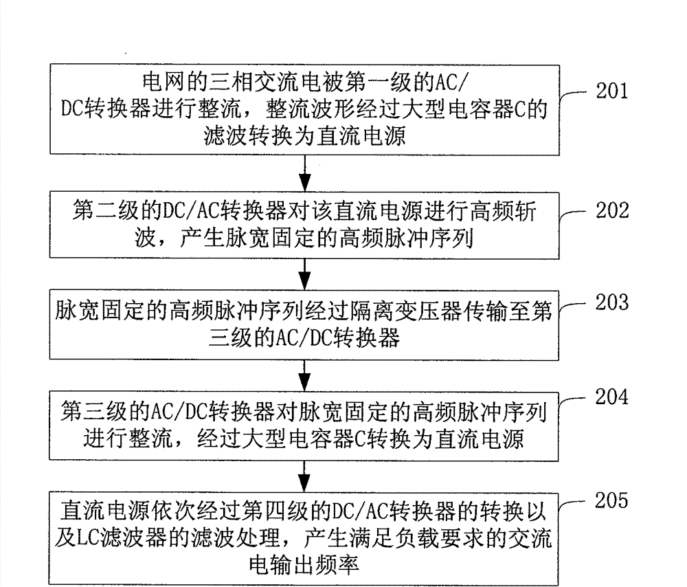
[0009] according to figure 1 As can be seen from the above description, when the power converter in the prior art is used for input / output frequency conversion, since the power converter includes 4 AC-DC converters, it is necessary to perform mutual conversion between 4 levels of DC and AC , and each stage of conversion will lead to the loss of conversion efficiency, therefore, the conversion efficiency of the final power converter will be greatly reduced, usually less than 85%
[0010] Furthermore, in the process of converting the input / output frequency of the power converter in the prior art, the power supply needs to exist in the DC state for many times, which means that multiple large capacitors C need to be used to filter the rectified waveform to obtain This dc state, due to the use of multiple large capacitors, results in a bulky, costly and low lifetime power converter
[0011] Furthermore, since the AC / DC converters inside the power converter in the prior art are all unidirectional rectifiers, it is difficult to apply to various output frequency requirements of various loads

Method used


Image

  • Power converter and input/output frequency conversion method
  • Power converter and input/output frequency conversion method
  • Power converter and input/output frequency conversion method

Examples


Embodiment 1

[0095] This embodiment 1 is to use Figure 7 The power converter of the shown structure is used for input / output frequency conversion.

[0096] Figure 9 is a flow chart of input / output frequency conversion in Embodiment 1 of the present invention. see Figure 9 ,use Figure 7 In the power converter of the present invention with the structure shown, the process of performing input / output frequency conversion specifically includes the following steps:

[0097] Step 901: The three-phase AC power A, B, C from the grid is respectively input to each phase of the three-phase bridge circuit composed of six bidirectional switches (1 to 6) in the first-stage AC / AC converter.

[0098] Step 902: Perform full-wave rectification on the three-phase alternating current, and perform real-time high-frequency chopping on the real-time rectified waveform according to the principle that the volt-second products of each pulse are the same during the rectification process to generate a high-fre...

Embodiment 2

[0108] This embodiment 2 is to use Figure 8 The power converter of the shown structure is used for input / output frequency conversion.

[0109] Figure 11 is a flow chart of input / output frequency conversion in Embodiment 2 of the present invention. see Figure 8 and Figure 11 ,use Figure 8 In the power converter of the present invention with the structure shown, the process of performing input / output frequency conversion specifically includes the following steps:

[0110] Step 1101: The three-phase AC power A, B, C from the power grid is respectively input to each phase of the uncontrolled rectifier bridge composed of IGBTs instead of commonly used three-phase diodes in the first-stage AC / AC converter.

[0111] Step 1102: Perform full-wave rectification on the three-phase AC.

[0112] see Figure 8 , the specific implementation of this step includes: in the rectification module of the first-stage AC / AC converter, control the turn-on and turn-off of six unidirectional...


PUM


Abstract

The invention discloses a power converter and an input / output frequency conversion method. The power converter comprises a first-stage AC / AC converter, a transformer, a second-stage AC / AC converter and an LC filter, wherein the first-stage AC / AC converter rectifies three-phase alternating current from a power grid, and carries out high-frequency chopping on the rectified waveform according to the principle that volt-second products of all pulses are equal, thereby generating a high-frequency pulse sequence; the transformer isolates the high-frequency pulse sequence generated by the first-stage AC / AC converter and outputs to the second-stage AC / AC converter; the second-stage AC / AC converter converts the high-frequency pulse sequence output by the transformer into a pulse sequence fundamental wave frequency of which is the required output frequency; and the LC filter filters the pulse sequence output by the second-stage AC / AC converter to obtain alternating current with the required output frequency. The power converter eliminates the direct current state in the power conversion process, and can complete the input / output frequency conversion process, which can be only completed by the combined actions of four stages of converters and two large-scale capacitors in the prior art, by using two stages of converters, thereby greatly enhancing the frequency conversion efficiency.

Description

technical field [0001] The invention relates to power supply technology, in particular to a power converter and an input / output frequency conversion method. Background technique [0002] The frequency of the mains power supply is standard 50Hz. However, in many application fields, the power frequency that needs to be used is not the 50Hz of the grid power supply, but other specific frequencies. For example, in railway applications, a power frequency of 25Hz is widely used for condition sensitivity test circuits; in aircraft station tests, the electronics used require a power frequency of 400Hz. In this way, in a specific application, it is necessary to use a power converter to convert the standard 50 Hz frequency of the power provided by the grid into an actual required frequency, that is, to perform input / output frequency conversion. [0003] figure 1 It is a structural schematic diagram of a power converter in the prior art. figure 2 It is a flowchart of input / output ...

Claims


Application Information

Patent Timeline
Patent Type & Authority Patents(China)
IPC IPC(8): H02M5/10H02M5/42H02M1/12
Inventor 吴学智姚吉隆赵研峰克晶宋英华
Owner SIEMENS CHINA
Learn More