
Automatic gain control method and device

A technology of automatic gain control and gain control signal, applied in the direction of gain control, amplification control, electrical components, etc., can solve the problems of affecting the receiving performance and degrading the receiving performance of the receiver, so as to improve the performance, shorten the gain convergence time, improve the Effect of Gain Convergence Speed

Active Publication Date: 2010-11-10
IND TECH RES INST
View PDF8 Cites 11 Cited by
  • Summary
  • Abstract
  • Description
  • Claims
  • Application Information

AI Technical Summary

Problems solved by technology

[0005] However, in the mobile channel environment, the automatic gain controller continuously adjusts the signal strength within the symbol cycle time during the process of stably tracking the signal strength change and immediately compensating for the path loss, resulting in the introduction of additional jitter noise and degrading the receiving performance of the receiver.
For example, the existing automatic gain controllers, such as those proposed in U.S. Patent Nos. 7,336,743, 7,295,073, 7,031,409, and 6,574,292, all use the system operating frequency to periodically adjust the gain. In a mobile environment, additional jitter noise is introduced to degrade the performance of the receiver. Receive performance, so it is greatly affected by nonlinear noise and mobile channel
[0006] All in all, in order to improve the gain convergence speed, the existing automatic gain controller cannot effectively take into account the problem of introducing noise when tracking path loss changes, which greatly affects its receiving performance in a mobile environment

Method used


Image

  • Automatic gain control method and device
  • Automatic gain control method and device
  • Automatic gain control method and device

Examples


Embodiment Construction

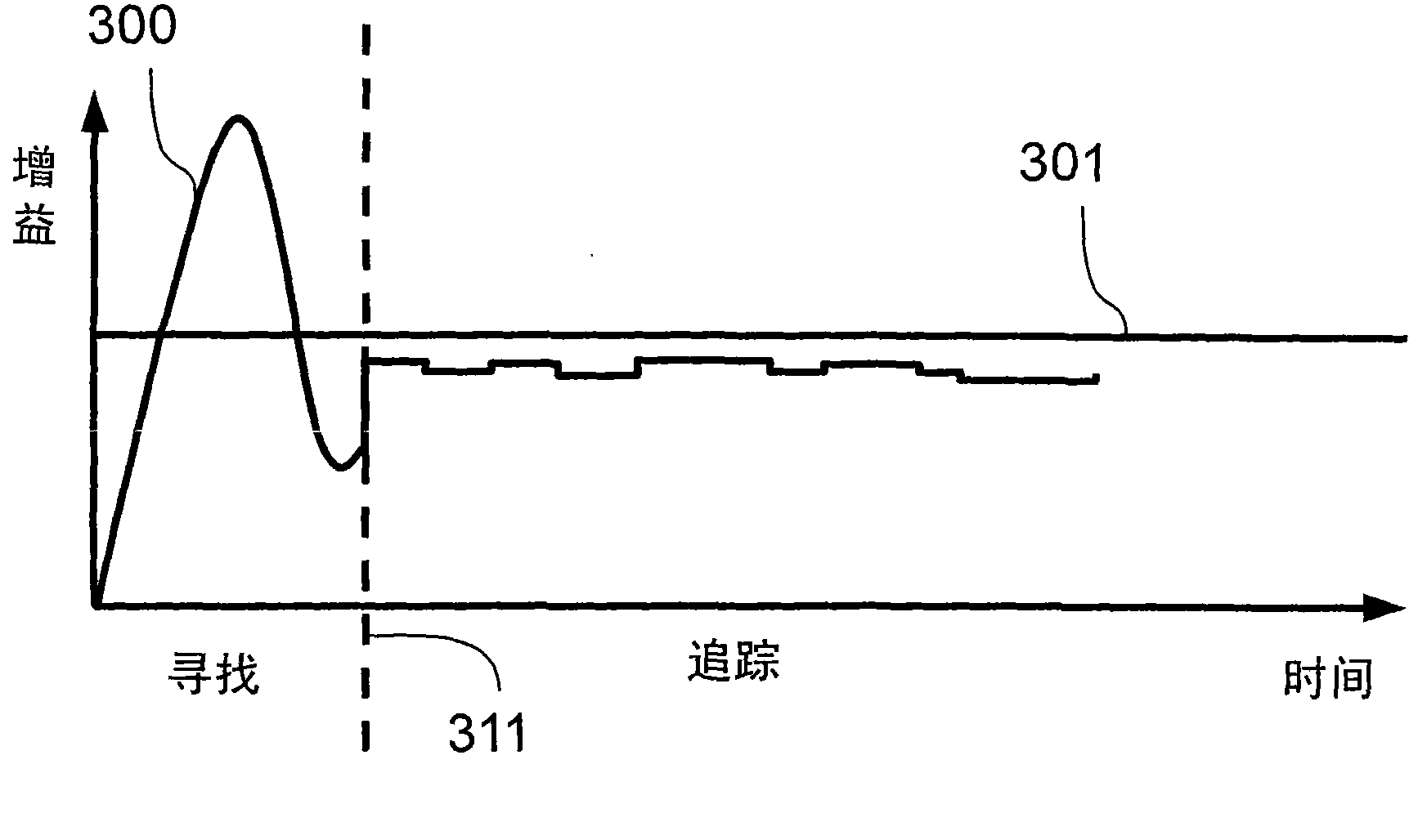
[0078] Different embodiments of the automatic gain control method of the present invention respectively propose a seeking mode, a tracking mode and combinations thereof, so as to improve the gain convergence speed under various receiving environments. In addition, the automatic gain control method of the present invention is applied to an embodiment of a mobile receiving environment, which can reduce the impact of noise on the system while improving path loss compensation in the mobile receiving environment. Therefore, the signal receiving performance is improved.

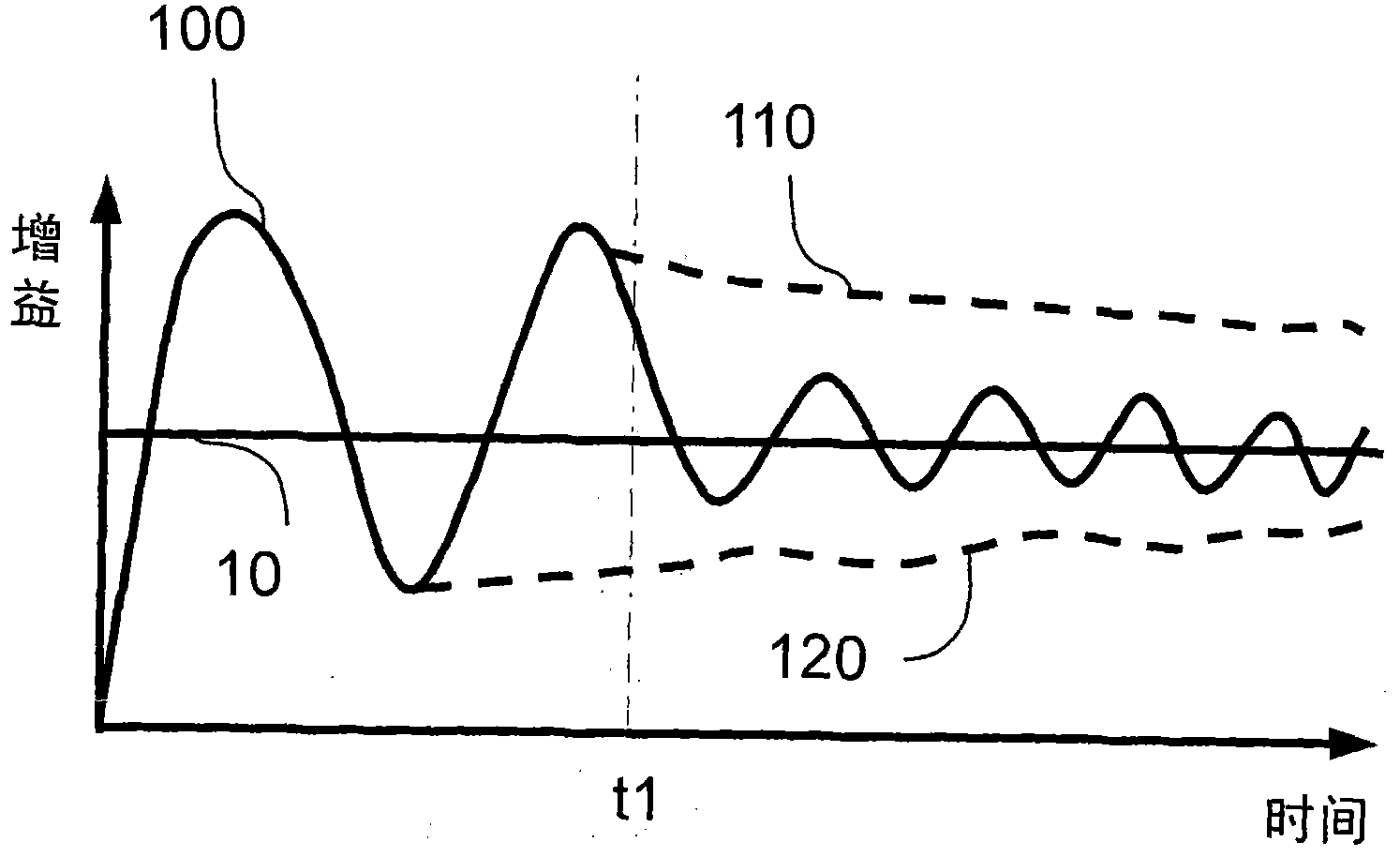
[0079] In the communication system, the gain curve of the gain value of the automatic gain controller is in the process of convergence, and the gain value is controlled by an automatic gain control method to be adjusted, such as figure 1 The gain curve 100 shown generally has a characteristic of oscillating up and down at the ideal level of 10. An embodiment of the method of the present invention is to enter a sea...


PUM


Abstract

The invention discloses an automatic gain control method and an automatic gain control device, which are used for controlling a gain value of a received signal. The method comprises the following step of: at the same time of regulating and converging the gain value, entering a searching mode to additionally change the gain value at least once to make the gain value approximate to a target level according to at least one characteristic value of relation indicating the change of the gain value with time. In another embodiment, the method further comprises the step of: entering a tracking mode to make the regulation period of gain longer than that before in a periodical gain regulation way so as to reduce introduced noise energy in the tracking of signal strength. Therefore, the embodiment of the invention can improve gain convergence speed, further reduce the influence of noises to a communication system in a mobile receiving environment and improve signal receiving efficiency.

Description

technical field [0001] The invention relates to a processing method and a signal receiving device of a received signal. Background technique [0002] Communication systems generally refer to systems that use signal strength or its derivative values ​​for demodulation and decoding, including wired and wireless communication systems, broadcasting and access communication systems. In a general communication system, the signal strength fluctuates under different channels due to the influence of channel characteristics. If the strength of the received signal at the receiving end is adjusted through an automatic gain controller, the received signal can be maintained within a fixed strength range to avoid The receiving end misjudged the message of the received signal. [0003] However, in an actual system, the signal strength adjusted by the automatic gain controller is not perfectly fixed as the above assumption. The Gaussian channel environment is used to illustrate the operati...

Claims


Application Information

Patent Timeline
Patent Type & Authority Applications(China)
IPC IPC(8): H03G3/20H04B1/12
Inventor 侯信安
Owner IND TECH RES INST
Learn More