EAST-ICRF (Experimental Advanced Superconducting Tokamak-Ion Cyclotron Resonant Heating) transmitter impedance matching and regulating system

An impedance matching and adjustment system technology, applied in transmission systems, electrical components, etc., can solve the problems of insufficient accuracy, time-consuming and laborious adjustment of RF transmitter matching network, etc., and achieve the effect of strong anti-interference ability.

Inactive Publication Date: 2010-11-10
赵洪亮
View PDF0 Cites 10 Cited by
  • Summary
  • Abstract
  • Description
  • Claims
  • Application Information

AI Technical Summary

Problems solved by technology

[0003] The purpose of the present invention is to provide a new control method for the time-consuming and la...

Method used


Image

  • EAST-ICRF (Experimental Advanced Superconducting Tokamak-Ion Cyclotron Resonant Heating) transmitter impedance matching and regulating system
  • EAST-ICRF (Experimental Advanced Superconducting Tokamak-Ion Cyclotron Resonant Heating) transmitter impedance matching and regulating system
  • EAST-ICRF (Experimental Advanced Superconducting Tokamak-Ion Cyclotron Resonant Heating) transmitter impedance matching and regulating system

Examples


Embodiment Construction

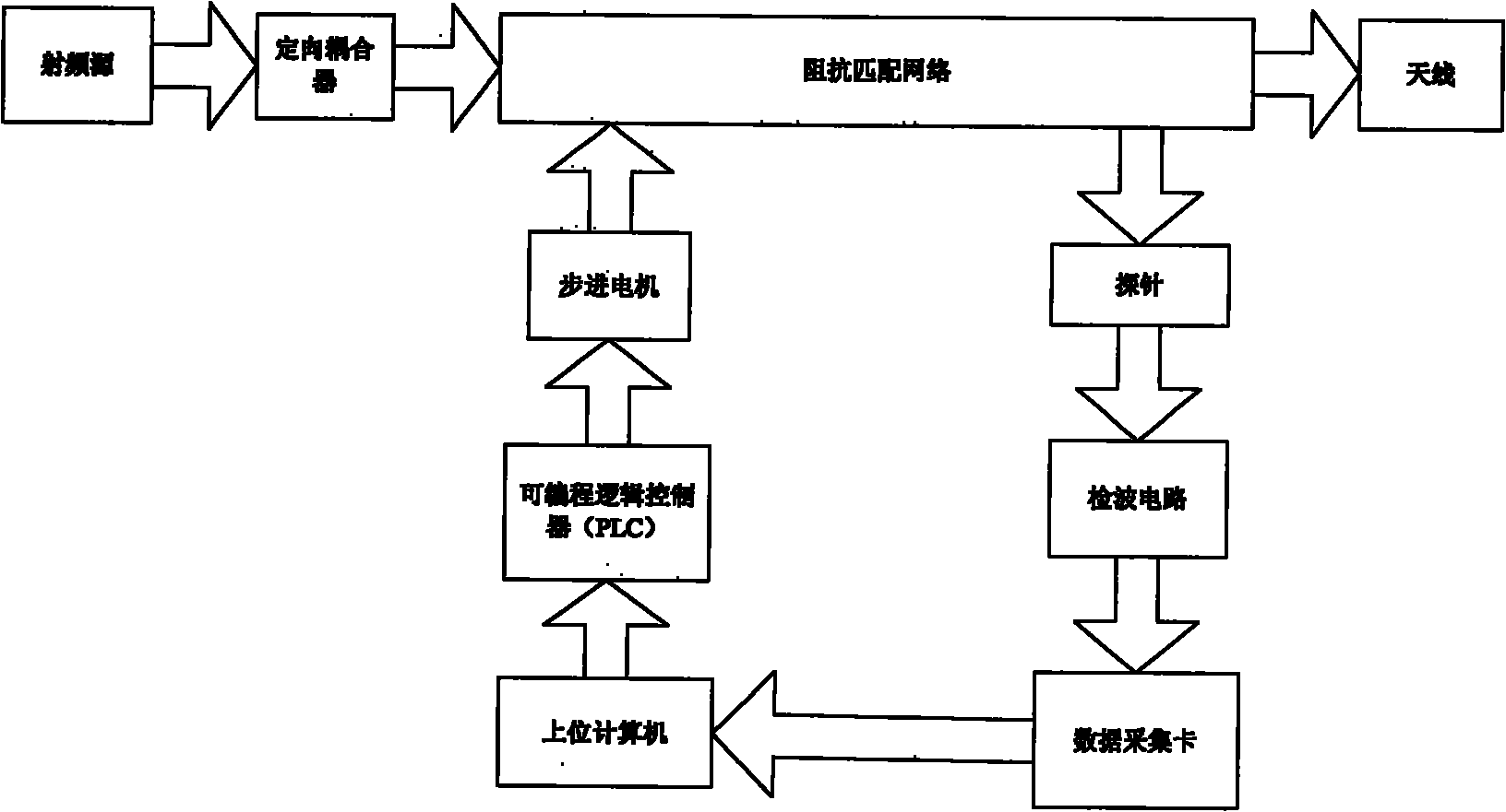
[0010] See attached figure 1 . Impedance matching network adjustment system, including: directional coupler, double branch, coaxial transmission line, probe, data acquisition card, host computer, programmable logic controller (PLC), stepper motor, detection circuit. Working frequency 20MHz-110MMz. The coupling degree of the probe to the radio frequency signal should be measured with a network analyzer; considering the accuracy of the measurement, the relationship between the DC output of the detection circuit and the radio frequency input has been tested and recorded, and the relationship can be given by a fitting method . In this way, during the entire adjustment process, for the upper computer, there is a definite relationship between the input and output of data, and the entire adjustment process can be smoothly carried out by using the program in the upper computer.

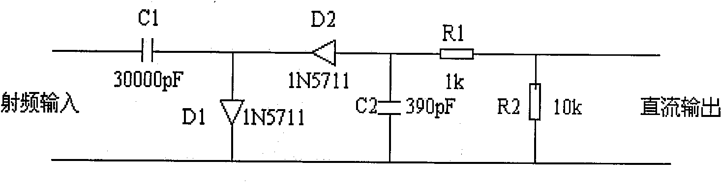
[0011] refer to figure 2 Schematic diagram of the detection circuit. It consists of high-frequency c...


PUM


Abstract

The invention discloses a transmitter impedance matching and regulating system which mainly solves the problems of complicated regulating operation, poor regulating precision, no flexibility and long consumed time when the transmitter impedance is not matched. The regulating system comprises a directional coupler, double branch sections, a coaxial transmission line, a probe, a data acquisition card, an upper computer, a programmable logic controller (PLC), a stepper motor and a detecting circuit, wherein the upper computer realizes an algorithm of a control process by adopting the LabVIEW engineering control software, and obtains a good man-machine interaction interface.

Description

technical field [0001] The invention relates to a wireless transmitter, especially suitable for a high-power radio frequency signal transmitter Background technique [0002] Impedance matching is the most widespread problem in the RF microwave field. The matching network generally used is only suitable for a fixed operating frequency, or has only a small relative bandwidth. Matching can be completed in a frequency band, and the state can be changed in real time, which requires a complete set of real-time control system. In the past, the adjustment and matching method was mainly through the calibration of the equipment in advance, and the adjustment was based on the experience value, which took a long time and was not easy to adjust. The long-term effect of the reflected signal may burn out the signal source. Contents of the invention [0003] The purpose of the present invention is to provide a new control method for the above problems of time-consuming and labor-intensi...

Claims


Application Information

Patent Timeline
IPC IPC(8): H04B1/04
Inventor 赵洪亮
Owner 赵洪亮
Why Eureka
Try Eureka