Tail gas collecting and exhausting device for automobile assembly lines

An assembly line and tail gas collection technology, applied in the direction of smoke removal, cleaning methods and appliances, chemical instruments and methods, etc., can solve the problems of short service life, air pollution, blackened equipment, etc., to reduce the air volume of the fan and facilitate exhaust and load-bearing, good collection and discharge effects

Active Publication Date: 2010-11-17
武汉东研智慧设计研究院有限公司
View PDF4 Cites 8 Cited by
  • Summary
  • Abstract
  • Description
  • Claims
  • Application Information

AI Technical Summary

Problems solved by technology

[0004] 1. The natural emission type has a lot of air pollution in the workshop, especially the current diesel engine vehicles, when the vehicle is started for the first time, it will produce thicker black smoke, which is within a range of about 50 meters before and after the off-line station. There is a strong car exhaust smell, and equipment in this area will be blackened in a short time
[0005] 2. The casing collection and discharge type cannot adapt to the mixed-flow assembly of multiple varieties of automobiles. At present, it is impossible for each automobile factory to produce only a single type of vehicle in one line, and the positions and sizes of the exhaust ports of various models are different. Especially For models with upper exhaust, the casing exhaust type is difficult to operate, and the service life of this type of equipment is too short, and the failure rate is also high
[0006] 3. The power and energy consumption of the down-drawing, collecting and discharging fan is large, and the exhaust gas collection and emission effect of the models with the upper and side outlets is very poor, and it only has a certain effect on the rear-discharged models

Method used


Image

  • Tail gas collecting and exhausting device for automobile assembly lines
  • Tail gas collecting and exhausting device for automobile assembly lines
  • Tail gas collecting and exhausting device for automobile assembly lines

Examples


Embodiment Construction

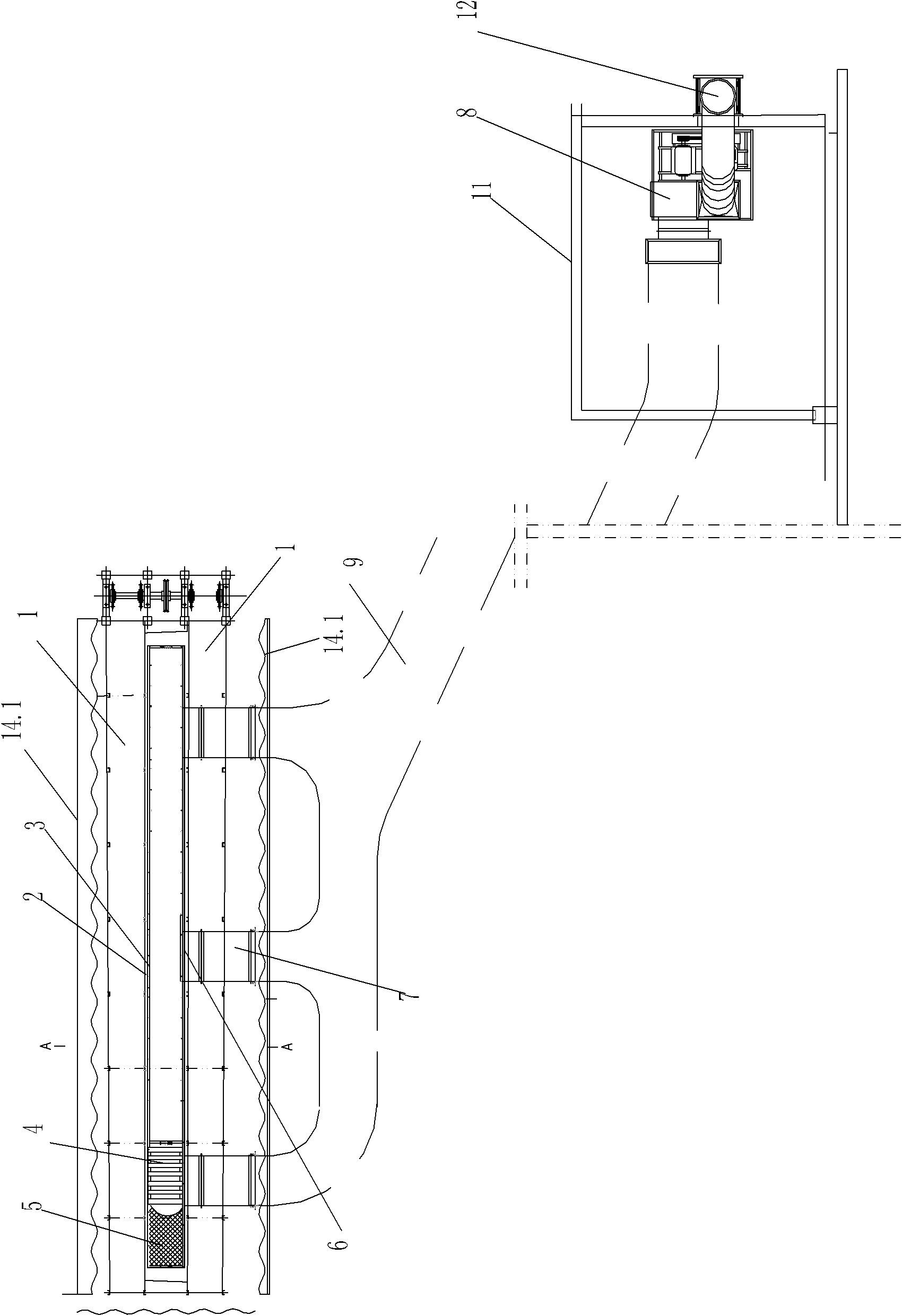
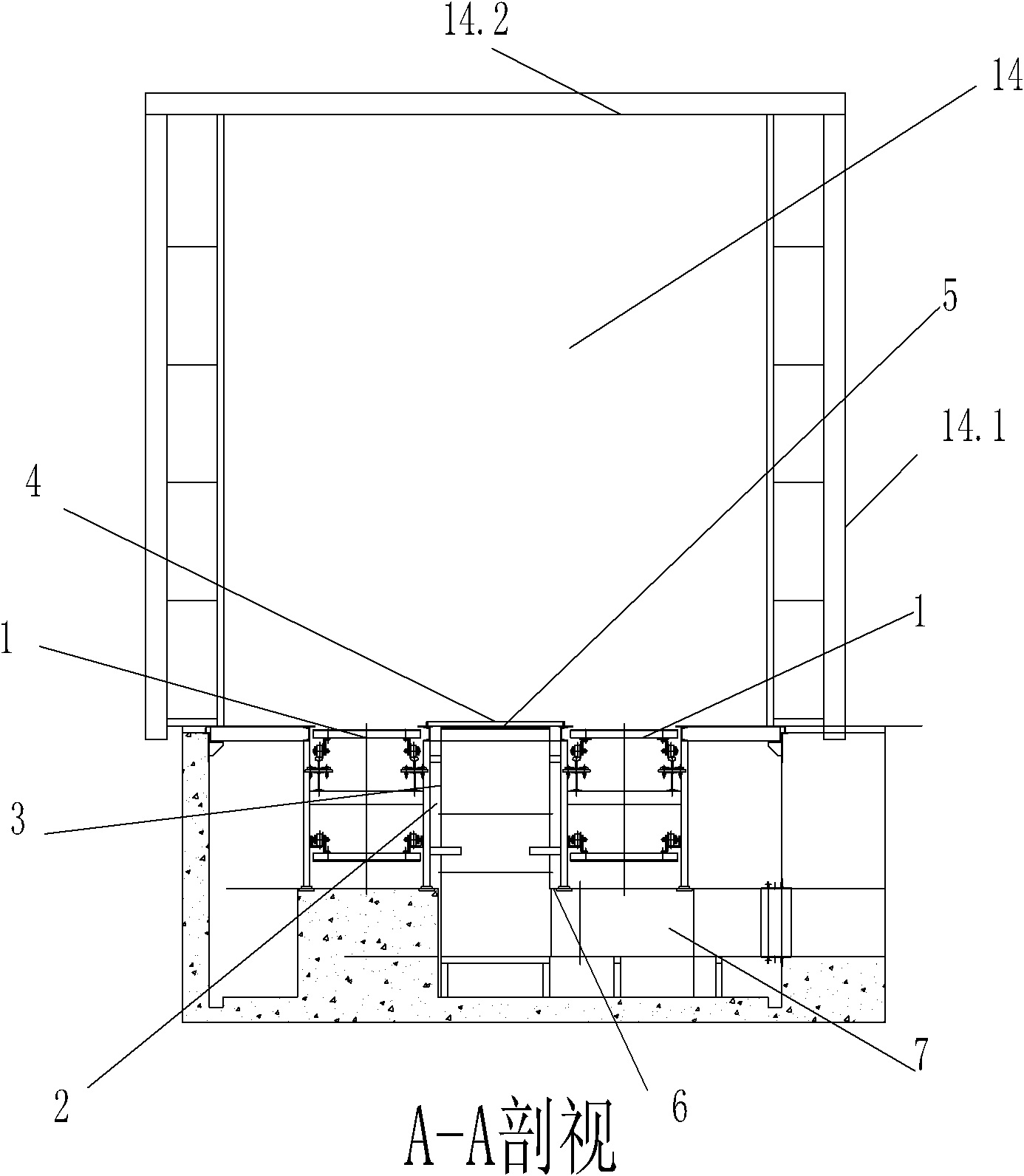
[0027] Such as figure 1 , 2 As shown, the automobile conveyor plate chain 1 is a conveying device for conveying automobiles on a complete vehicle assembly line, and it is an existing device in an existing complete vehicle assembly workshop. A section of upper-opening exhaust gas collection and exhaust duct 2 is set between the automobile conveyor plate chain 1 at the start-off station after the complete vehicle assembly is completed at the end. The exhaust gas collection and exhaust duct 2 is set under the ground, and the exhaust gas is collected and exhausted. The side partitions and bottom partitions of the trench 2 are galvanized plates to form the inner wall of the exhaust gas collection and exhaust duct 2 with low flow resistance; the upper opening of the exhaust gas collection and exhaust duct 2 is covered with a grid plate 4 ( It is arranged along the length direction of the exhaust gas collection and exhaust channel), the upper opening of the exhaust gas collection and e...


PUM


Abstract

The invention discloses a tail gas collecting and exhausting device for automobile assembly lines, which comprises automobile conveying plate chains arranged on the indoor ground, wherein a section of tail gas collecting and air exhausting channel with an upper opening is arranged between the automobile conveying plate chains; a grating plate is covered on the upper opening of the tail gas collecting and air exhausting channel; exhaust holes are formed on the wall and/or the bottom of the tail gas collecting and air exhausting channel; the exhaust holes are connected and communicated with an inner exhaust pipe; an exhaust blower is connected on the inner exhaust pipe; the gas outlet of the exhaust blower is connected with an outer exhaust pipe; the outer exhaust pipe is arranged outside; and an automobile tail gas collecting chamber cover with two open ends is arranged on the ground of the tail gas collecting and air exhausting channel. Because the chamber type collecting chamber cover is adopted, the blowing quantity of the blower can be greatly reduced, and simultaneously, the emission of automobile tail gas is effectively controlled. The invention well ensures that the air outside the chamber type collecting chamber cover can not be polluted, and simultaneously, the power of the blower is greatly reduced, thereby achieving the purpose of saving energy sources.

Description

Technical field [0001] The invention belongs to a vehicle assembly line device, and in particular relates to a commercial vehicle assembly line tail gas collecting and discharging device. Background technique [0002] In the assembly workshops of various automobile manufacturers in my country, serious air pollution occurs at the end of the assembly line at the end of the assembly line and the start-off station, especially at the end of the assembly line for commercial vehicles. . Because commercial vehicle exhaust outlets have various exhaust emission methods according to different models, such as upper row type, side row type, rear bottom row type and so on. [0003] The traditional exhaust gas collection and discharge methods include: natural discharge, sleeve collection and discharge, and downdraft collection and discharge. However, the traditional exhaust gas collection and discharge methods such as natural discharge, casing collection and discharge, and downdraft collection a...

Claims


Application Information

Patent Timeline
Patent Type & Authority Applications(China)
IPC IPC(8): B08B15/00
Inventor 俞开榜吴志强江蓉朱宝兰武永和
Owner 武汉东研智慧设计研究院有限公司
Why Eureka
Try Eureka