Check patentability & draft patents in minutes with Patsnap Eureka AI!

Cutting-off methods of edge gates in plastic moulds and moulds thereof

A technology of plastic molds and large spouts, applied in the field of plastic molds, can solve problems such as easy scratches on plastic parts, failure to replace large spouts, and no molds found, so as to improve production efficiency, increase profits, improve customer satisfaction, and average yield Enhanced effect

Inactive Publication Date: 2010-11-17
阳恒
View PDF7 Cites 21 Cited by
  • Summary
  • Abstract
  • Description
  • Claims
  • Application Information

AI Technical Summary

Problems solved by technology

[0002] Most of the Dashuikou injection molds now only rely on manual post-processing of the shear nozzle, and the remaining very few Dashuikou injection molds can rely on complex rows (also called sliders) and high costs such as fragile and expensive tools. Internal automatic water cutting port
Others such as needle-point thin nozzle, diving nozzle, banana nozzle (also called horn nozzle), half-banana nozzle (also called half-horn nozzle, a new nozzle between the diving inlet and banana nozzle), pin-point hot water Although the nozzle, needle valve type hot water outlet, etc. can have the function of automatic water cut-off in the mold, they are either expensive or have molding defects, so they cannot replace the large nozzle.
At present, more than 60% of the molds are ordinary large nozzles, and the separation between the nozzle and the product can be realized only by manual post-processing and cutting of the nozzle: in this way, the labor cost is high, and the difference in manual post-processing and cutting of the nozzle is large, and manual cutting of the nozzle requires a knife and plastic parts It is easy to scratch and not good, and people are also easy to be injured and fatigued
[0003] After retrieving the published literature, it is not found that there is a mold identical to this technology

Method used


Image

  • Cutting-off methods of edge gates in plastic moulds and moulds thereof
  • Cutting-off methods of edge gates in plastic moulds and moulds thereof
  • Cutting-off methods of edge gates in plastic moulds and moulds thereof

Examples


Embodiment 1

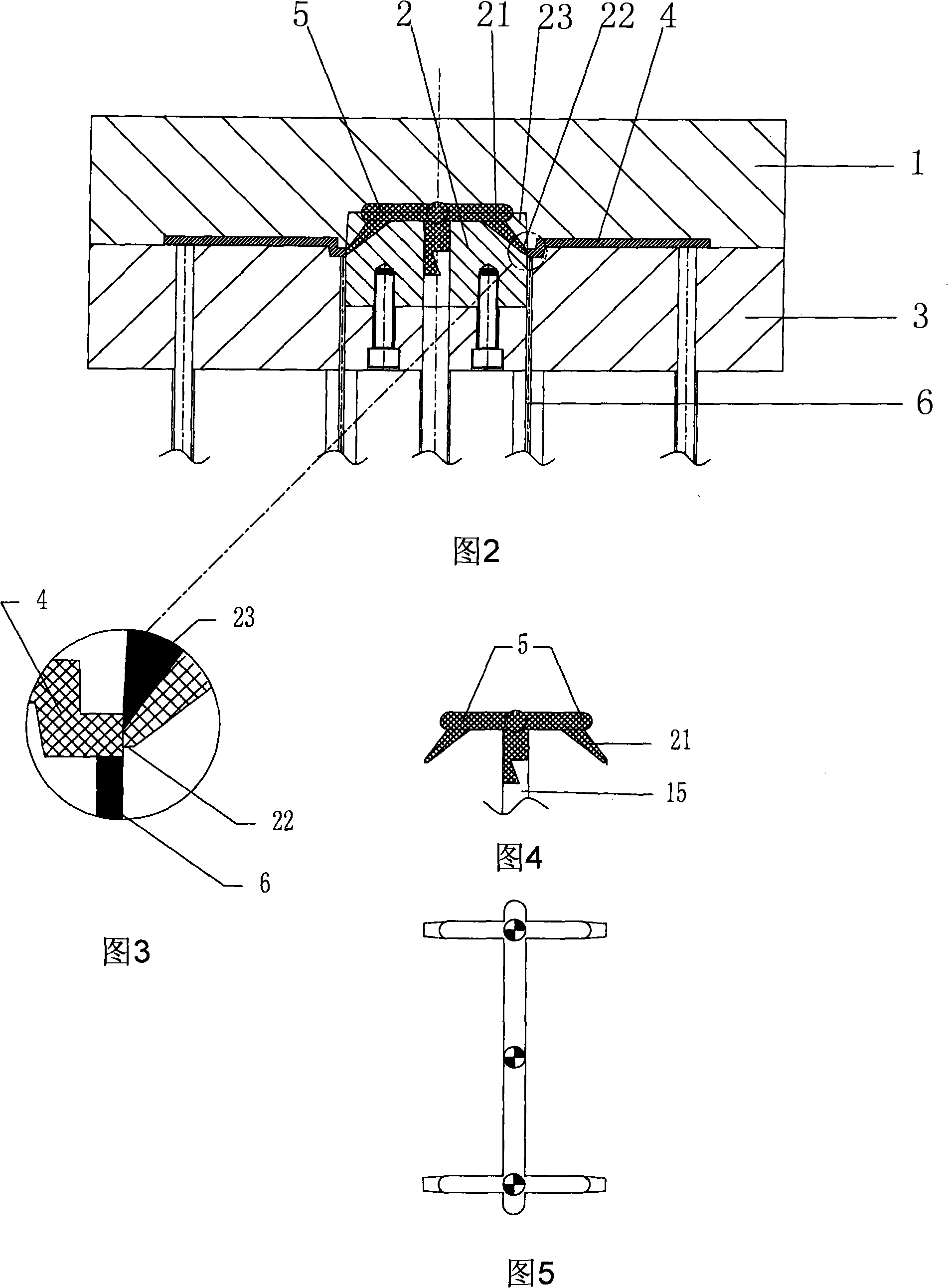
[0085] Embodiment 1; With reference to Figure 2-Figure 5 shown

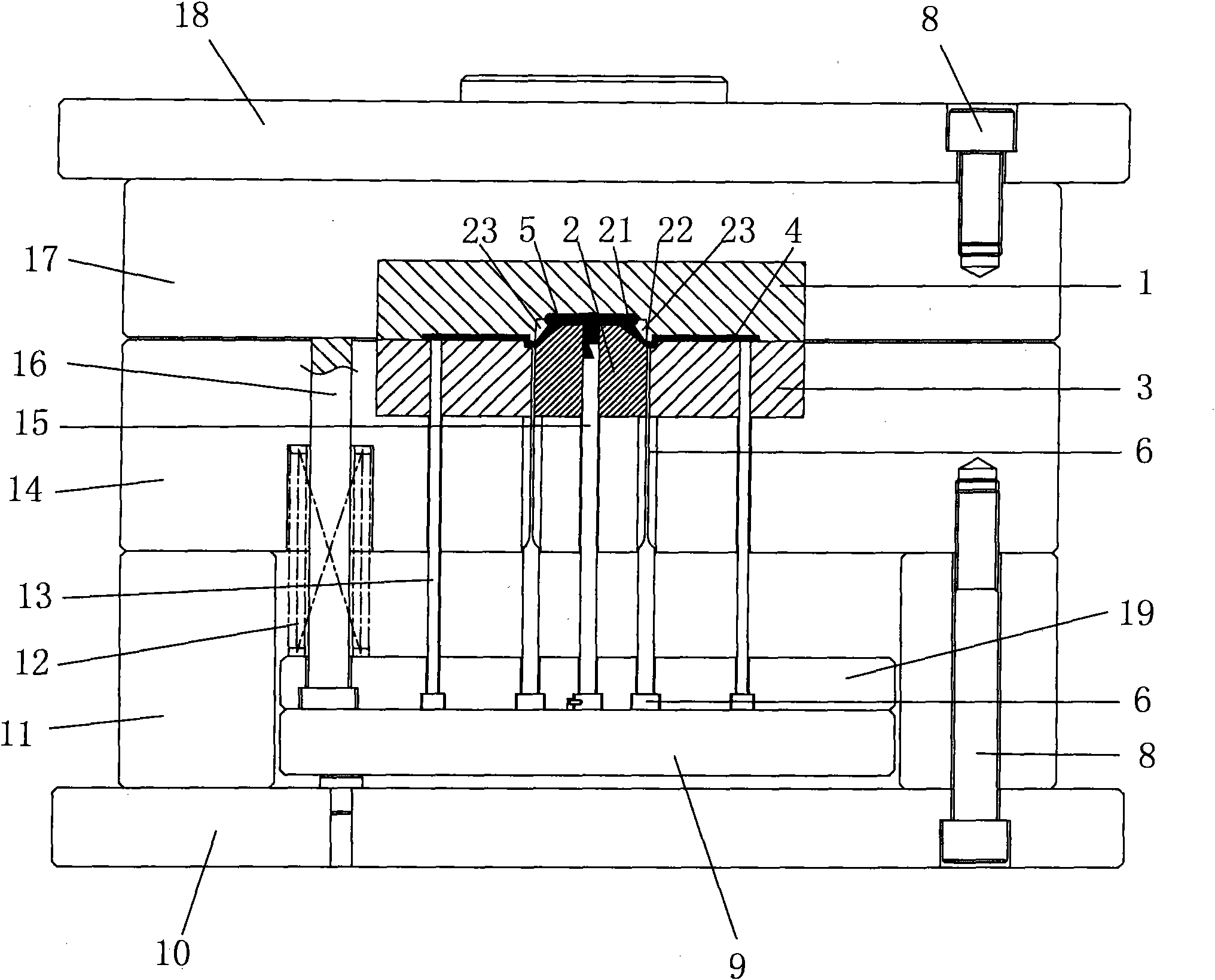
[0086] The main structure of this example is figure 1 The same, specifically reflected in the structure of the gate insert 2 of the large gate. Among them: the movable mold core 3 is provided with 2 acupuncture points of the large nozzle gate insert, the static mold core 1 is provided with the 2 acupoints of the large nozzle gate insert, and the static mold core is also provided with a main flow channel 5 in the static mold core acupuncture point. Dashuikou gate insert 2 is installed in the acupuncture point between the static mold core 1 and the moving mold core 3, the top surface of the Dashuikou gate insert 2 is provided with a main channel 5, and an undercurrent is provided on the main channel 5 Road 21, (the main channel 5 and the sub-runner 21 form a large nozzle), the large nozzle gate 22 of the sub-runner 21 is a flat gate, and the upper surface of the flat gate forms an acute-angled edge with an inner...

Embodiment 2

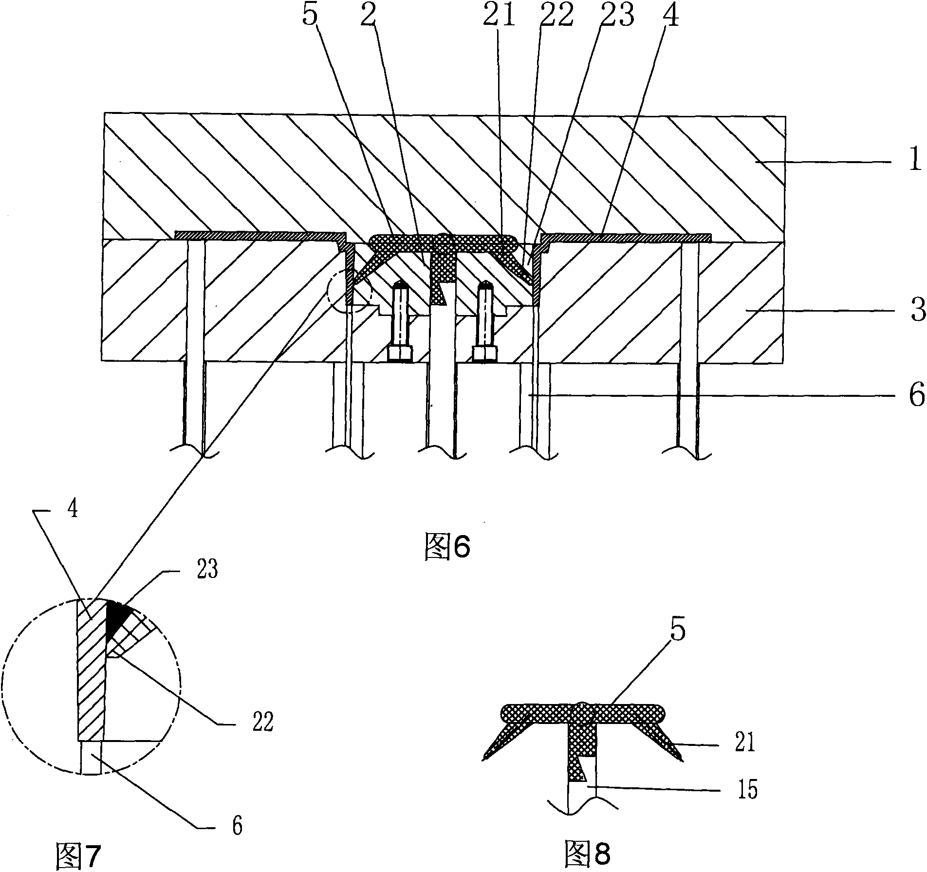
[0089] Embodiment 2; With reference to Figure 6-Figure 9 shown

[0090] The main structure of this example is figure 1 The same, specifically reflected in the structure of the gate insert 2 of the large gate. Among them: in the movable mold core 3, there are 2 acupoints for the large gate gate insert, on the parting surface of the static mold core 1, there is a main channel 5, and the large gate gate insert 2 is installed in the movable mold core 3 In the acupoints, the top surface of the gate insert 2 of the large water inlet is provided with a main channel 5, and an undercurrent channel 21 is arranged on the main channel 5, (the main channel 5 and the undercurrent channel 21 form a large water outlet), and the large water outlet of the undercurrent channel 21 The gate 22 is a flat gate, and the upper surface of the flat gate forms an acute-angled edge with an inner slope. The large gate gate 22 of the underrunner 21 of the main flow channel 5 is connected to the product c...

Embodiment 3

[0093] Embodiment 3; With reference to Figure 10-Figure 13 shown

[0094] The main structure of this example is figure 1 The same, specifically reflected in the structure of the gate insert 2 of the large gate. Among them: the movable mold core 3 is provided with 2 acupoints for the large nozzle gate insert, the static mold core 1 is provided with the 2 acupoints for the large nozzle gate insert, and the mold core 3 is also provided with a main flow channel 5, which is large. The nozzle gate insert 2 is installed in the acupuncture point between the static mold core 1 and the movable mold core 3, the bottom surface of the large gate gate insert 2 is provided with a main channel 5, and an undercurrent channel 21 is provided on the main channel 5 , (the sprue 5 and the sub-runner 21 form a large nozzle), the large nozzle gate 22 of the sub-runner 21 is a flat gate, and the lower surface of the flat gate forms an acute-angled edge with an inner slope, wherein the sprue 5 The ...


PUM


Abstract

The invention provides cutting-off methods of edge gates in plastic moulds and moulds thereof, wherein the cutting-off methods include an edge gate pouring gate mold inserting technique and an edge gate pouring gate hot melting extrusion technique. A mould 1 comprises a top plate, a bottom plate, a static template, a movable template, a thimble panel, a thimble backing plate, product thimbles, a static mould core, a movable mould core, an edge gate thimble and a flat thimble. A mould 2 comprises a static mould holder and a movable mould holder, wherein a static template, a movable template, a product thimble fixed plate, a product thimble top plate, a compression nozzle thimble fixed plate, a compression nozzle thimble top plate, a mould leg, a static mould core, a movable mould core, product thimbles, a compression nozzle thimble, an edge gate thimble and a return pole of the compression nozzle thimble top plate.

Description

technical field [0001] The invention relates to a plastic mold for an injection molding machine. One is to press and cut off the large nozzle by setting a large nozzle gate insert in the mold; The molten rubber material is extruded to cut off the large nozzle. Background technique [0002] Most of the Dashuikou injection molds now only rely on manual post-processing of the shear nozzle, and the remaining very few Dashuikou injection molds can rely on complex rows (also called sliders) and high costs such as fragile and expensive tools. Internal automatic water cutting port. Others such as needle-point thin nozzle, diving nozzle, banana nozzle (also called horn nozzle), half-banana nozzle (also called half-horn nozzle, a new nozzle between the diving inlet and banana nozzle), pin-point hot water Although the nozzle, needle valve hot water outlet, etc. can have the function of automatic water cut-off in the mold, they are either expensive or have molding defects, so they can...

Claims


Application Information

Patent Timeline
IPC IPC(8): B29C45/38B29C45/26B29C45/27
Inventor 阳恒
Owner 阳恒
Features
  • R&D
  • Intellectual Property
  • Life Sciences
  • Materials
  • Tech Scout
  • Unparalleled Data Quality
  • Higher Quality Content
  • 60% Fewer Hallucinations
Learn More