Thin-film solar cell

A technology of solar cells and thin films, applied in circuits, photovoltaic power generation, electrical components, etc., can solve problems such as backwardness

Inactive Publication Date: 2010-11-17
SCHOTT AG
View PDF8 Cites 11 Cited by
  • Summary
  • Abstract
  • Description
  • Claims
  • Application Information

AI Technical Summary

Problems solved by technology

However, the efficiency of commercial thin-film solar cells that have been obtained so far is still significantly behind that of crystalline silicon-based s

Method used


Image

  • Thin-film solar cell
  • Thin-film solar cell
  • Thin-film solar cell

Examples


Embodiment Construction

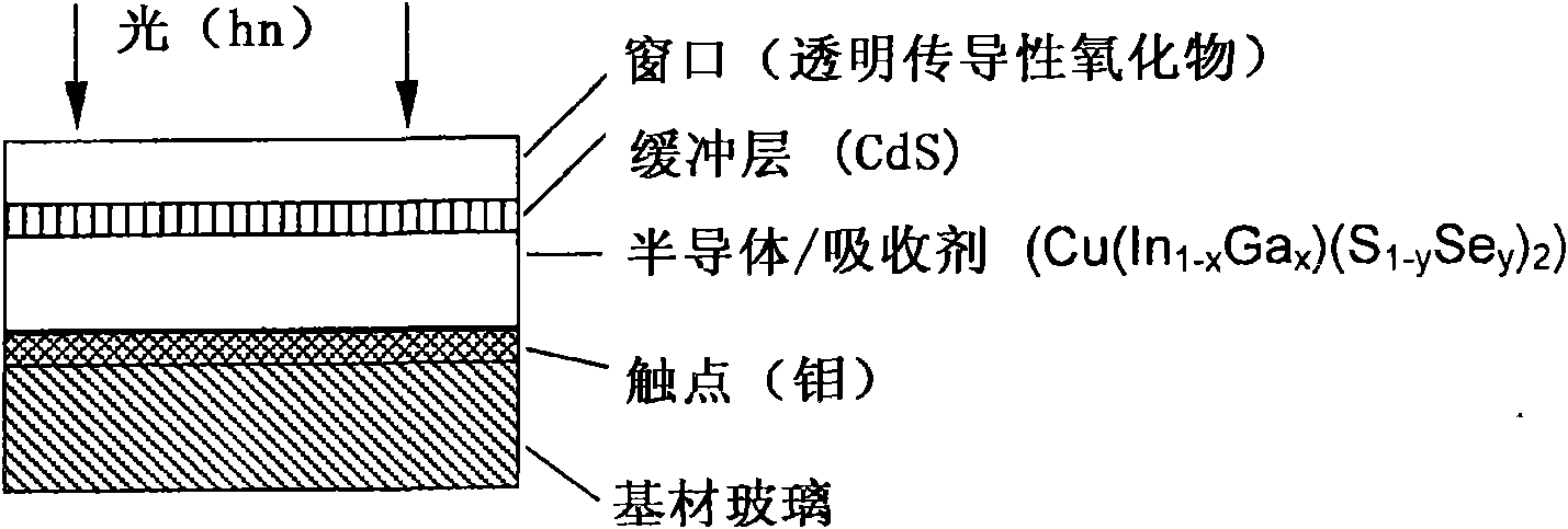
[0087] figure 1 Illustrates that the present invention has based on Cu (In 1-x Ga x )(S 1-y Se y ) 2 Schematic structure of a pn heterojunction planar thin-film solar cell.

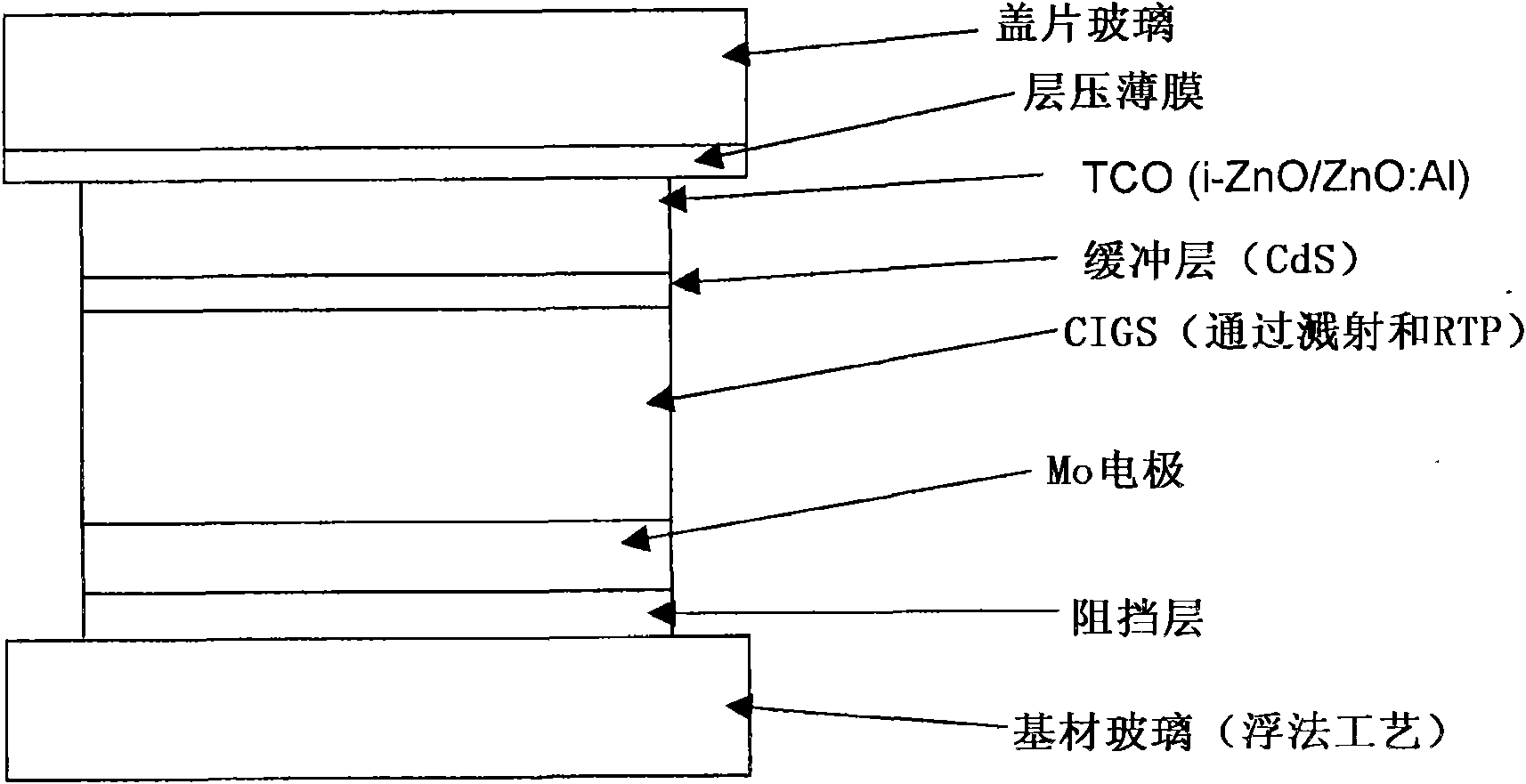
[0088] exist figure 1 In one embodiment shown in Table 2, a substrate glass having a glass composition of 2 and a Tg of 632°C was produced by a float process and cut into small pieces by a cemented carbide cutting tool. The substrate glass plate obtained in this way was cleaned according to standard industrial processes and coated with the following layer system: substrate glass / back contact (molybdenum, by sputtering technique) / absorber (CIGS, with Metal layer applied and subsequently reacted by "rapid thermal processing" in an environment containing chalcogens, RTP short, T 退火 >550°C) / buffer layer (CdS, by chemical bath deposition) / window layer (i-ZnO / ZnO:Al, by sputtering technique). Depending on the embodiment, module or solar cell, the integrated series connection is obtained by various inter...


PUM


Abstract

The claimed thin-film solar cell comprises at least one multicomponent substrate glass containing Na2O, said substrate glass containing less than 1 wt.% B2O3, less than 1 wt.% BaO and less than, in total, 3 wt.% CaO + SrO + ZnO. The molar ratio of the substrate glass components (Na2O+K2O)/(MgO+CaO+SrO+BaO) is greater than 0.95, the molar ratio of the substrate glass components SiO2/AI2O3 is less than 7, and the substrate glass has a transformation temperature Tg which is higher than 550 DEG C, in particular higher than 600 DEG C.

Description

technical field [0001] The present invention relates to thin film solar cells. Background technique [0002] The future market development of photovoltaic applications, especially for use in grid-connected photovoltaic power plants, depends critically on the potential to reduce the cost of solar cell production. Great potential is found in the production of thin-film solar cells, since significantly less photoactive material is required for the efficient conversion of sunlight into electricity than is the case with conventional crystalline, silicon-based solar cells. In thin-film solar cells, photoactive semiconductor materials, especially indirect semiconductors such as silicon-based materials (here, a distinction is made between amorphous or microcrystalline and crystalline silicon or layers thereof), direct semiconductors such as high Adsorptive compound semiconductors (such as CdTe) or highly adsorptive compound semiconductors of groups I to III to VI2, such as Cu(In 1...

Claims


Application Information

Patent Timeline
IPC IPC(8): C03C3/04C03C3/112C03C17/06H01L31/0749
CPCC03C3/112C03C17/3649H01L31/0749H01L31/035281C03C17/3605Y02E10/541C03C4/0092C03C17/3678H01L31/0392H01L31/03923H01L31/03925
Inventor 布克哈德·施派特伊夫琳·鲁迪吉尔-沃伊特沃尔夫冈·曼斯塔德西尔克·沃尔夫
Owner SCHOTT AG
Why Eureka
Try Eureka