Step swirling flow vertical shaft

A swirl shaft and ladder technology, which is applied in the field of swirl shafts with high water head and large flow, can solve the problems of increased cavitation and cavitation on the wall surface, difficulty in aeration, and high flow rate, so as to improve the energy dissipation rate and increase the resistance along the water flow Effect

Inactive Publication Date: 2010-11-17
SICHUAN UNIV
View PDF5 Cites 13 Cited by
  • Summary
  • Abstract
  • Description
  • Claims
  • Application Information

AI Technical Summary

Problems solved by technology

However, engineering practice shows that under the conditions of large flow and high water head, the following problems exist in the swirl shaft: 1) the flow velocity in the shaft is too high, and the risk of cavitation and cavitation on the wall surface increases; 2) due to the centrifugal force of the water flow, the conventional It becomes very difficult to aerate the annular aeration sill, and cannot play the role of aeration and corrosion reduction
Although the aeration effect of this kind of swirl shaft is obvious under the conditions of large flow and high water head, the water and air are fully mixed, the air content of the water flow is greatly increased, the flow state of the water flow is stable, and the cavitation cavitation damage on the shaft wall is eliminated, but The energy dissipation rate needs to be further improved

Method used


Image

  • Step swirling flow vertical shaft
  • Step swirling flow vertical shaft
  • Step swirling flow vertical shaft

Examples


Embodiment 1

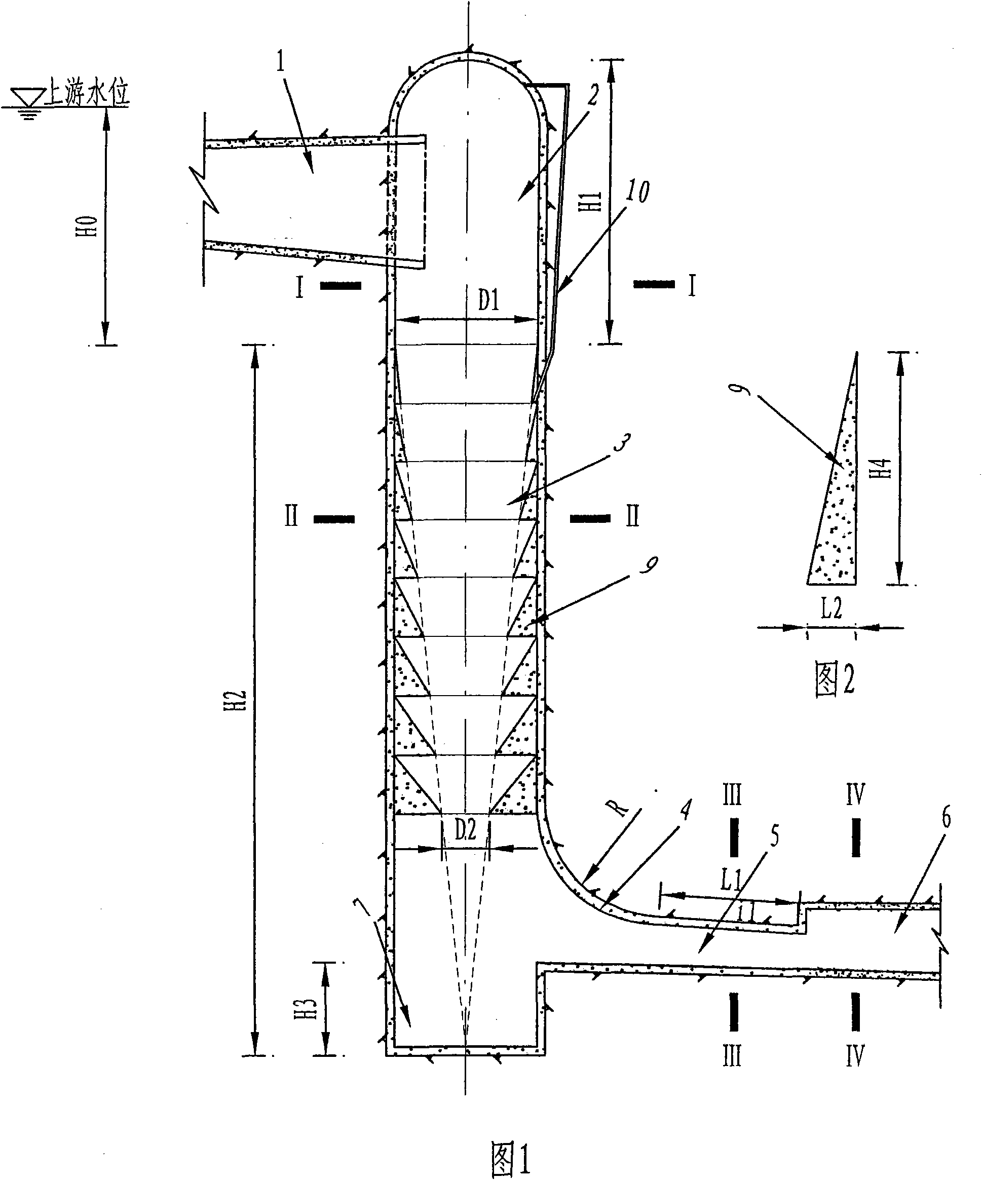
[0026] The stepped swirl shaft in this example is designed according to the spillway tunnel of a hydropower station project. In the case of checking the flood, the design flow of the spillway tunnel is 543m 3 / s, the top elevation is 2495m, and the vertical shaft section with stepped energy dissipators starts to be connected at 2365m, and the floor elevation of the vertical shaft spillway tunnel is 2245m.

[0027] In this embodiment, the structure of the ladder swirl shaft is as follows figure 1 , Figure 5 As shown, it includes a vortex chamber section 2 and a vertical shaft section 3 connected to the vortex chamber section; the vortex chamber section 2 is provided with a water inlet for tangentially introducing the water flow in the channel 1 into the vortex chamber; the vertical shaft section 3, a stepped energy dissipator 9 is provided on the well wall of the shaft. The stepped energy dissipator 9 is composed of eight steps with the same height. Large and small conical f...

Embodiment 2

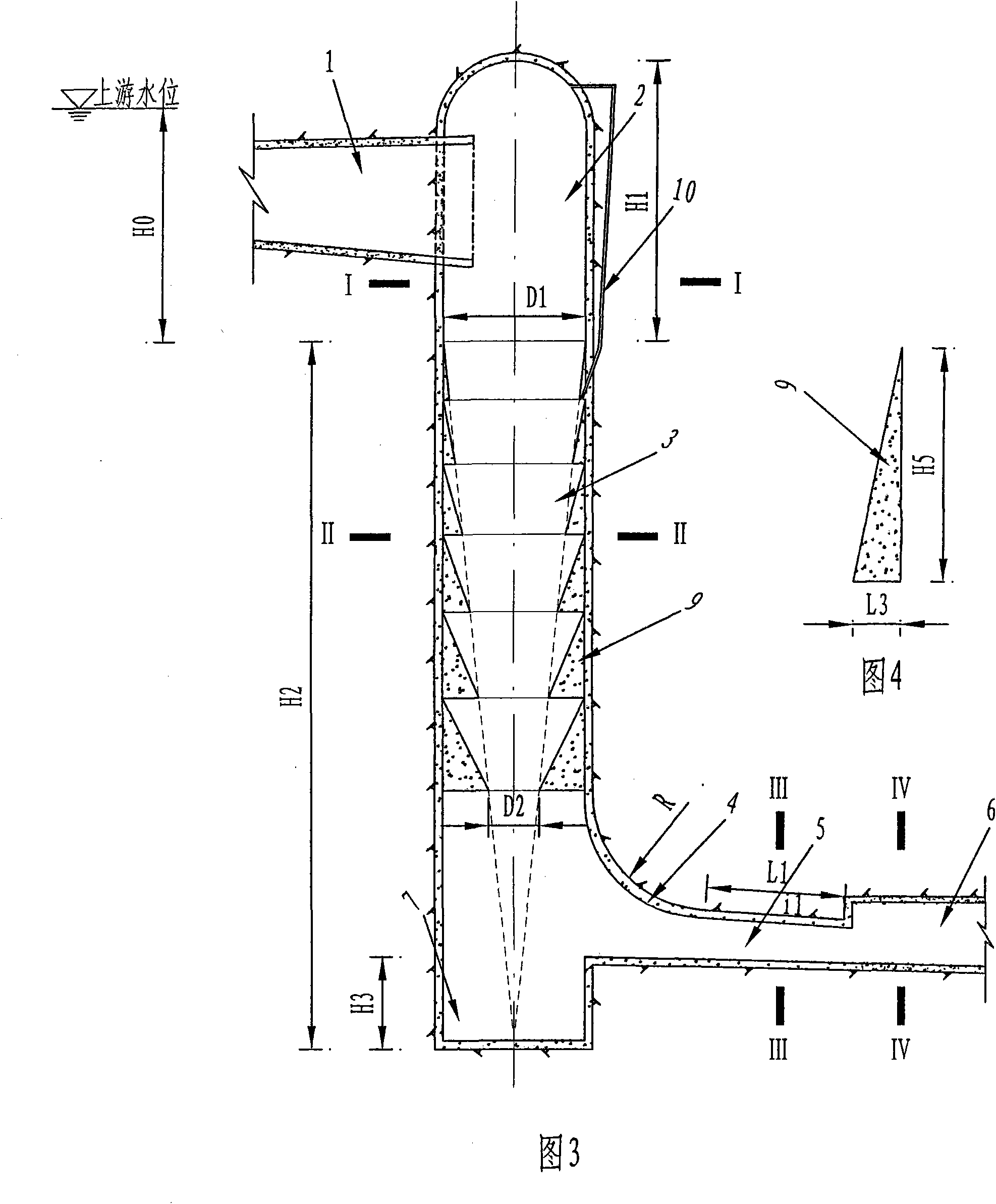
[0031] The stepped swirl shaft in this embodiment is designed according to the spillway tunnel of a hydropower station project. In the case of checking the flood, the design discharge volume of the spillway tunnel is 870m 3 / s, the top elevation is 2425m, and the vertical shaft section with stepped energy dissipators starts to be connected at 2390m, and the bottom plate elevation of the vertical shaft flood discharge tunnel is 2245m.

[0032] In this embodiment, the structure of the ladder swirl shaft is as follows image 3 , Figure 5 As shown, it includes a vortex chamber section 2 and a vertical shaft section 3 connected to the vortex chamber section; the vortex chamber section 2 is provided with a water inlet for tangentially introducing the water flow in the channel 1 into the vortex chamber; the vertical shaft section 3. A stepped energy dissipator 9 is set on the shaft wall of 3. The stepped energy dissipator 9 is composed of seven steps whose heights are proportional ...


PUM


Abstract

The invention relates to a step swirling flow vertical shaft. The vertical shaft comprises a vortex chamber section and a vertical shaft section connected with the vortex chamber section, wherein the vortex chamber section is provided with a water inlet used for introducing the water stream of an approach channel in a vortex chamber tangentially; the vertical shaft section is a cylinder, the bottom end of the vertical shaft section is provided with a baffle well, the lower part of the vertical shaft is communicated with a flood discharge tunnel through a flip bucket and a pressing slope section; the wall of the vertical shaft is provided with a step energy dissipater; the first step of the step energy dissipater is provided with an air vent, the air vent is communicated with the top of the vortex chamber section through a vent pipe; and the bumps of the step sections of the step energy dissipater are arranged on the line connecting the starting point of the first step with the centre of the bottom of the vertical shaft to form a obconical flow passage, thus increasing the revolution of water stream, reducing the flow rate of water stream, increasing the pressure on the wall of the shaft and avoiding damages caused by cavitation.

Description

technical field [0001] The invention belongs to a swirl shaft used in water conservancy and hydropower projects, in particular to a swirl shaft suitable for high water head and large flow. Background technique [0002] The vortex shaft is a new type of flood discharge and energy dissipation facility. Since the water flow from the diversion channel enters the vortex chamber from the tangential direction of the vortex chamber section, it rotates around the axis of the shaft and flows close to the wall, forming a stable cavity in the center of the shaft, thus maintaining the water flow. The flow state is stable and good ventilation conditions can be formed. However, engineering practice shows that under the conditions of large flow and high water head, the following problems exist in the swirl shaft: 1) the flow velocity in the shaft is too high, and the risk of cavitation and cavitation on the wall surface increases; 2) due to the centrifugal force of the water flow, the conve...

Claims


Application Information

Patent Timeline
Patent Type & Authority Applications(China)
IPC IPC(8): E02B8/06
Inventor 张建民许唯临刘善均王韦曲景学邓军刘璐陈剑刚
Owner SICHUAN UNIV
Why Eureka
Try Eureka