
Strip line filter, and method for manufacturing the same

A filter and stripline technology, applied in waveguide-type devices, electrical components, circuits, etc., can solve the problems of filter characteristic variation, yield drop, electrode burr or peeling, etc., to achieve stable filter characteristics and high-quality products. rate, the effect of suppressing component size

Inactive Publication Date: 2010-11-17
MURATA MFG CO LTD
View PDF6 Cites 2 Cited by
  • Summary
  • Abstract
  • Description
  • Claims
  • Application Information

AI Technical Summary

Problems solved by technology

Due to this change, poor connection of electrodes or changes in filter characteristics may occur, so the yield of products may drop
[0008] In addition, due to the deviation of the cut-off position when cutting out each filter, the electrode size of the wide-width electrode part of the resonance line fluctuates greatly, resulting in fluctuations in filter characteristics, and the product yield may decrease.
In addition, due to cutting, burrs or peeling may occur in the electrode, which may also cause fluctuations in filter characteristics, and product yield may decrease

Method used


Image

  • Strip line filter, and method for manufacturing the same
  • Strip line filter, and method for manufacturing the same
  • Strip line filter, and method for manufacturing the same

Examples


Embodiment Construction

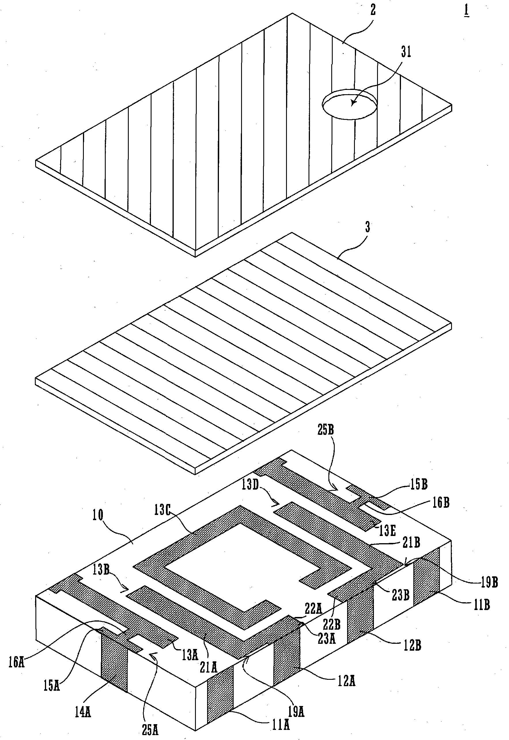
[0029] Hereinafter, a configuration example of the stripline filter according to the embodiment of the present invention will be described.

[0030] The stripline filter shown here is a bandpass filter. This filter is used in UWB (Ultra Wide Band) communication corresponding to a high frequency band of 4 GHz or higher.

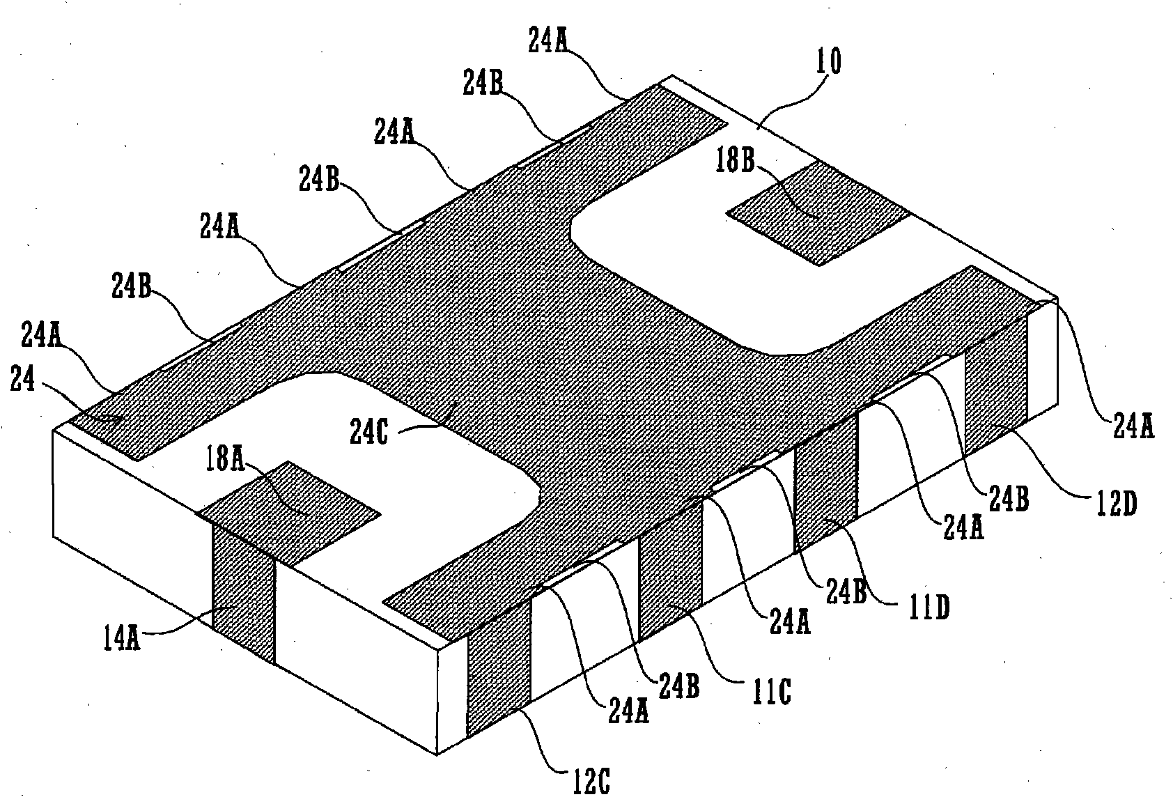
[0031] figure 2 It is an exploded perspective view of the upper surface side of the stripline filter. image 3 It is a perspective view of the lower surface side of the stripline filter.

[0032]The stripline filter 1 has a dielectric substrate 10 and glass layers 2 , 3 . Here, the glass layers 2 , 3 each have a thickness of approximately 15 μm. The glass layers 2 and 3 are laminated on the upper surface of the dielectric substrate 10, and are used for mechanical protection of the stripline filter 1, improvement of weather resistance, and the like. Since the glass layer 2 is laminated on the glass layer 3 , the hole 31 serving as an indicator can be prov...


PUM


Abstract

Disclosed is a strip-line filter, which suppresses an element size while realizing a high conformity with arbitrary stable filter characteristics. The strip-line filter (1) comprises generally L-shaped upper-face resonance lines (13B and 13D). These upper-face resonance lines (13B and 13D) include connecting electrode portions (23A and 23B), first line portions (22A and 22B) and second line portions (21A and 21B). The connecting electrode portions (23A and 23B) are formed with a larger width than the line width of side-face resonance lines (12A and 12B). The individual line portions (21A, 21B, 22A and 22B) confront the edges of the corners belonging to an upper-face resonance line (13C), individually through spacings. The first line portions (22A and 22B) are arranged, at the edges on the end sides of a dielectric substrate (10), to confront the end sides of the dielectric substrate (10) through the spacings, excepting the portions connected with the connecting electrode portions (23A and 23B).

Description

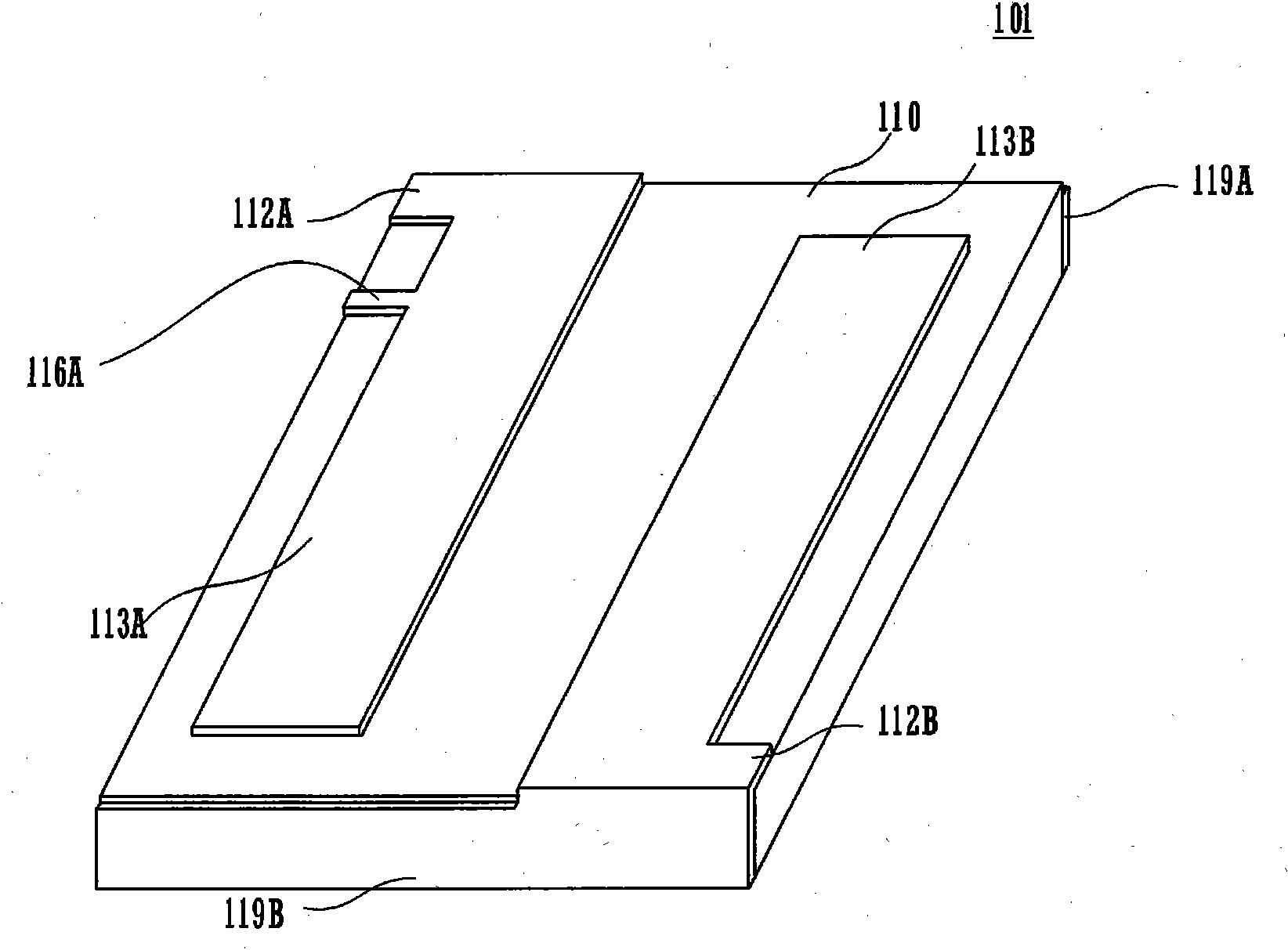
technical field [0001] The present invention relates to a stripline filter provided with striplines on a dielectric substrate and a method of manufacturing the same. Background technique [0002] A stripline filter in which a stripline resonator is provided on a dielectric substrate is used in various fields (for example, refer to Patent Document 1). [0003] Here, the configuration of a conventional stripline filter will be described. figure 1 It is the top perspective view of the stripline filter. [0004] In stripline filter 101 , resonant lines 113A and 113B are formed on the upper surface of dielectric substrate 110 . The resonant line 113A is a 1 / 4 wavelength resonant line, and is connected to a ground electrode (not shown) on the lower surface of the dielectric substrate 110 via an electrode 119A formed on the rear surface in the figure. The resonant line 113B is a 1 / 4 wavelength resonant line, and is connected to a ground electrode (not shown) on the lower surface...

Claims


Application Information

Patent Timeline
Patent Type & Authority Applications(China)
IPC IPC(8): H01P1/203H01P11/00
CPCH01P1/20381H01P1/20354H01P11/007
Inventor 本田修祥辻口达也竹井泰范
Owner MURATA MFG CO LTD
Learn More