
Radiotherapy positioning device

A radiation therapy and positioning device technology, which is applied in radiation therapy, treatment, patient positioning for diagnosis, etc., can solve the problems of inability to correct the unexpected movement of the patient in real time, the complicated process of 3D image reconstruction, and the increase of the psychological pressure of the patient, etc., to avoid The effect of lagging machine response, simple and convenient equipment, and small occupied space

Inactive Publication Date: 2010-11-24
江苏同庚电子科技有限公司
View PDF6 Cites 25 Cited by
  • Summary
  • Abstract
  • Description
  • Claims
  • Application Information

AI Technical Summary

Problems solved by technology

The radiotherapy positioning method and device realize continuous radiotherapy positioning through continuous scanning of the radiotherapy couch laser during the radiotherapy process, which solves the problem that the existing radiotherapy positioning method and device cannot correct the unexpected movement of the patient's body position in real time during the treatment process. question
However, the above-mentioned radiotherapy positioning method and device still have the following deficiencies. The first is that a radiotherapy couch laser capable of three-dimensional scanning needs to be installed, and the equipment is relatively expensive; Three-dimensional scanning takes a long time to scan; the third is that after laser scanning, it needs to be input into the computer and reconstruct the three-dimensional image. The reconstruction process of the three-dimensional image is complex and time-consuming
The second and third points are undoubtedly complicated and prolong the whole radiotherapy process, increase the psychological pressure of patients during radiotherapy, and may cause more side effects

Method used


Image

  • Radiotherapy positioning device
  • Radiotherapy positioning device
  • Radiotherapy positioning device

Examples


Embodiment 1

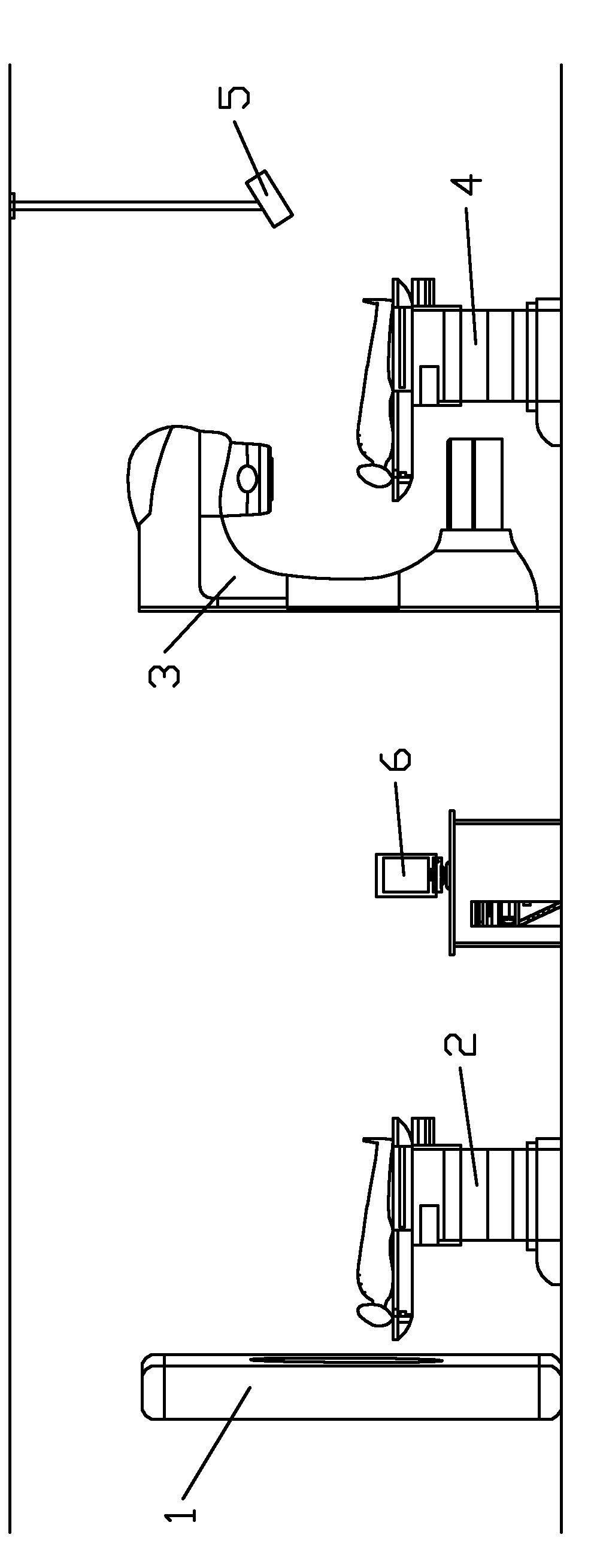
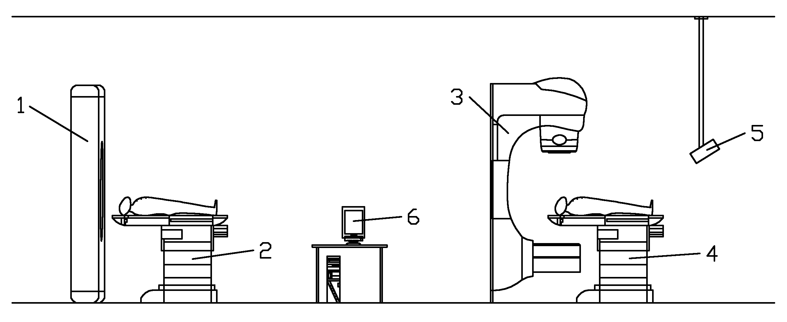
[0031] (Example 1) see figure 1 , the radiotherapy positioning device of the present embodiment comprises CT machine 1, CT bed 2, radiotherapy machine 3, radiotherapy couch 4, computer 6 and a time-of-flight camera 5, CT machine 1, CT couch 2, radiotherapy machine 3, radiotherapy couch 4 , time-of-flight camera 5 are all connected with computer 6 .

[0032] CT machine 1 is the medical facility "computerized tomography camera" used for scanning in the hospital. CT machine 1 scans a certain part of the human body at a certain thickness through the X-ray beam. Absorbed by tissues, part of the rays pass through the human body and are received by the detection organs to generate signals. Because the density of various tissues of the human body is different, the penetration ability of X-rays is different, so the rays received by the detector are different. After converting the received ray signals with differences into digital information, the computer will process them and output...


PUM


Abstract

The invention discloses a radiotherapy positioning device comprising a CT (Computer Tomography) machine, a CT bed, a radiotherapy machine, a radiotherapy bed, a time flying camera and a computer connected with the members. The time flying camera is fixedly arranged right at the rear upper part of the radiotherapy bed and is opposite to the radiotherapy machine. The time flying camera is a real-time 3D mapping camera based on the time flying principle and can realize real-time three-dimensional imaging on the patients. In a computer, tumor position information in the CT three-dimensional imageobtained by scanning the CT machine is guided into the real-time three-dimensional image captured by the time flying camera so as to drive the radiotherapy bed to move by the computer according to the position of the tumor in the real-time three-dimensional image and perform accurate and located radiotherapy by the radiotherapy machine. By adopting the single-lens camera, the positioning device can realize real-time three-dimensional imaging on the patients, and has rapid positioning speed, good instantaneity and lower cost.

Description

technical field [0001] The invention relates to a precise positioning device and a positioning method for radiotherapy. Background technique [0002] Radiation therapy is radiation therapy, which refers to the use of rays to eliminate lesions, and radiation such as X-rays, γ-rays, and electron rays to irradiate cancer tissues. Due to the biological effects of radiation, it can kill cancer tissues in the largest amount, destroy cancer tissues, and make them shrink. As an important means of treating malignant tumors, radiotherapy can produce good results for many cancers. [0003] However, during radiation therapy, the radiation will also affect the normal tissue in the treatment area, causing damage to normal cell tissue and causing corresponding side effects. [0004] Therefore, in the course of radiotherapy, it is necessary to accurately locate the patient's tumor location, so as to minimize the damage of radiotherapy to normal tissues. At present, precise positioning dev...

Claims


Application Information

Patent Timeline
IPC IPC(8): A61B6/00A61B6/04A61B6/03A61N5/00
Inventor 李云杨军
Owner 江苏同庚电子科技有限公司
Learn More