Method for detecting and compensating floor-type boring and milling machine space position by using double-frequency laser measurement system

A measurement system, dual-frequency laser technology, applied in measurement devices, optical devices, other manufacturing equipment/tools, etc., can solve the problems of machine tool manufacturing precision accuracy error, poor product stability, verticality change, etc., to improve accuracy and The effect of stability

Inactive Publication Date: 2010-11-24
SHENJI GRP KUNMING MACHINE TOOL
View PDF5 Cites 9 Cited by
  • Summary
  • Abstract
  • Description
  • Claims
  • Application Information

AI Technical Summary

Problems solved by technology

However, due to factors such as the softness of the foundation, the settlement change of the foundation, and the weight of the machine tool itself, there will be slight changes in the foundation and the bed. For example, the horizontal guide rail of the machine tool is not completely parallel to the horizontal plane. , the verticality of the column of the machine tool to the horizontal plane may change; the second is that the manufacturing accuracy of the machine tool itself also has precision errors. , and when the ram seat moves up 3m along the machine column, the center point of the boring bar has an error of 0.06mm in the horizontal direction before and after the movement
These two kinds of errors are reflected when the machine tool is working, and the specific performance is that it affects the accuracy of the processed parts and the poor stability of the product.

Method used


Image

  • Method for detecting and compensating floor-type boring and milling machine space position by using double-frequency laser measurement system
  • Method for detecting and compensating floor-type boring and milling machine space position by using double-frequency laser measurement system
  • Method for detecting and compensating floor-type boring and milling machine space position by using double-frequency laser measurement system

Examples


Embodiment Construction

[0018] The present invention will be further described below in conjunction with the accompanying drawings and examples, but the examples do not limit the present invention.

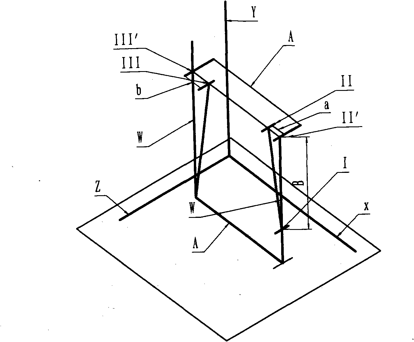
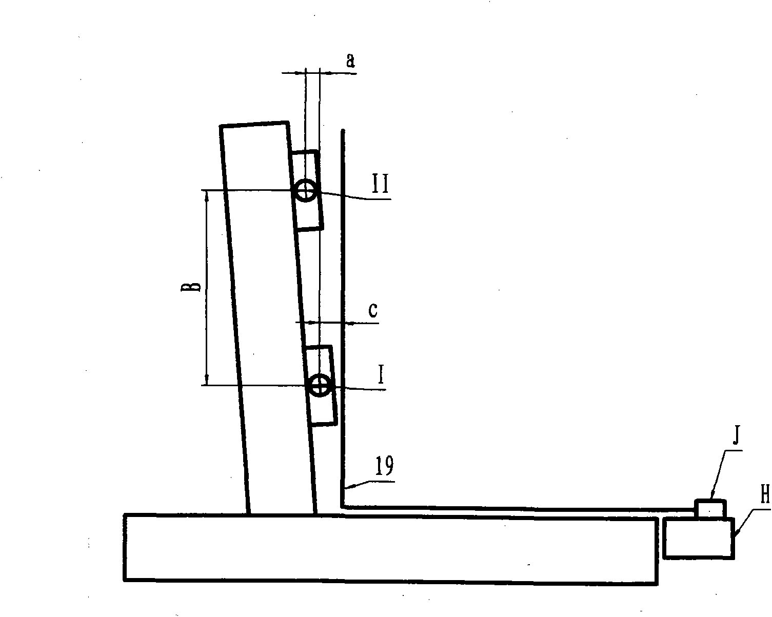
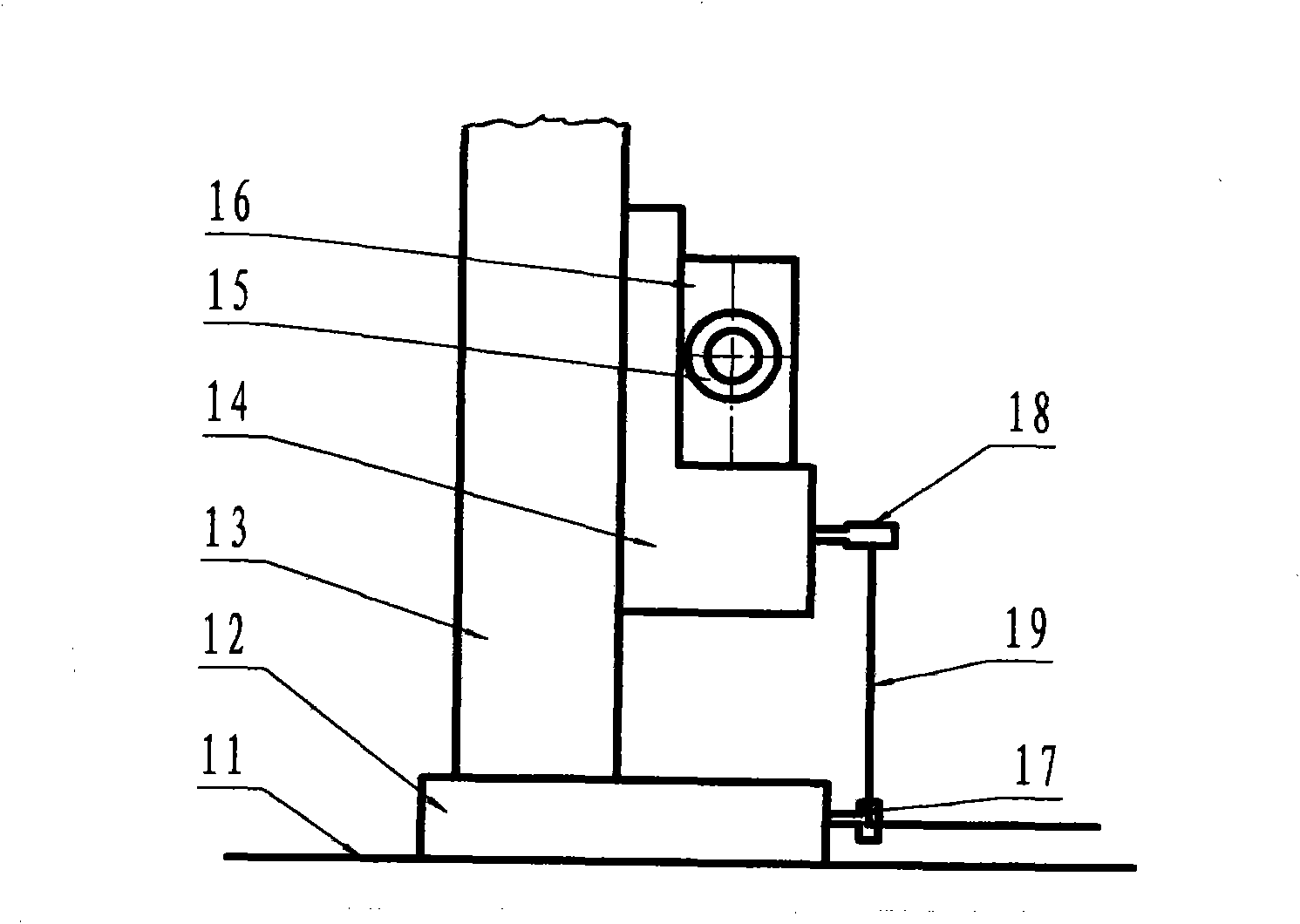
[0019] Embodiment, with the same floor boring and milling machine (model is TK6920) the test piece before adopting this method and after adopting this method is processed, then on the three-coordinate inspection instrument, the test piece obtained by processing is detected, with It illustrates the effect of this method on improving the precision and stability of the machined parts. During the machining, the machine column and the ram seat are moved. Figure 4 It is the processing drawing of the test piece, and the distance between adjacent holes of ①, ②, ③, and ④ is 1000mm. For the first time, the cutting test piece is subjected to conventional cutting, that is, the cutting without error compensation, and the obtained cutting test piece is tested on the three-coordinate inspection instrument. Based on th...


PUM


Abstract

The invention discloses a method for detecting and compensating a floor-type boring and milling machine space position by using a two-frequency laser measurement system, and belongs to the field of numerical control machines. In the method, a fixed datum plane is established on a tip of a horizontal lathe guide rail of the numerical control floor-type boring and milling machine, a laser generator of a double-frequency laser interference measurement system which is provided with a computer is fixed on the datum plane, a laser beam emitted by the laser generator is controlled to be higher than the plane of the lathe guide rail, a lower sliding seat of the lathe is provided with a vertical conversion lens, the laser beam emitted by a double-frequency laser generator is conversed by the conversion lens into a vertically upward laser beam, and an interference target lens is arranged on a ram seat of the lathe; and the position of the central point of a boring bar is taken as the first positioning point when an upright column of the lathe and the ram seat are at certain positions, the points of new positions of the upright column of the lathe and the ram seat after movement are taken as second and third positioning points, the laser beam emitted by the double-frequency laser generator is utilized to measure an error due to lathe precision and foundation variation, and the error is compensated by a numerical control system of the lathe, so that the machining precision of the numerical control floor-type boring and milling machine is improved.

Description

technical field [0001] The invention relates to a method for precisely correcting and compensating the positioning of each space position of a floor boring and milling machine tool when a large metal cutting floor boring and milling machine tool is in use, and specifically relates to using a precision dual-frequency laser interferometry system to detect each space position of a CNC floor boring and milling machine And the method for carrying out precision correction on it belongs to the technical field of numerical control floor machine tool manufacturing. Background technique [0002] A large floor boring and milling machine refers to a large working machine placed on the ground. When the machine tool is installed on the ground, the theory requires its horizontal guide rail to be parallel to the horizontal plane, and it will remain unchanged during the machining of the machine tool. The column of the machine tool is required to be always perpendicular to the guide rail, tha...

Claims


Application Information

Patent Timeline
Patent Type & Authority Applications(China)
IPC IPC(8): B23Q23/00G01B11/02
Inventor 刘可
Owner SHENJI GRP KUNMING MACHINE TOOL
Why Eureka
Try Eureka